
1 Components of a Disk
1.1 Platters:
- Circular, flat disks made from aluminum, glass, or ceramic materials.
- Covered with a magnetic coating where data is stored.
1.2. Read/Write Heads:
- Small electromagnets used to read and write data on the platters.
- Positioned above and below each platter.
- Moves across the surface of the platter to access different tracks.
1.3. Actuator Arm:
- Holds the read/write heads.
- Moves the heads across the platters to the desired track.
1.4. Spindle:
- Rotates the platters at a constant speed (measured in revolutions per minute, RPM).
- Typically, disks rotate at speeds between 5,400 and 15,000 RPM.
1.5. Controller Board:
- Manages the data transfer between the disk and the computer.
- Controls the movement of the actuator arm and the rotation of the platters.
- Converts analog signals from the read/write heads into digital data.
2 CHS (Cylinder - Head - Sector)
It is an early method for giving addresses to each physical block of data on a hard disk drive.
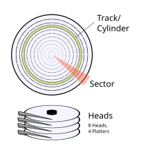
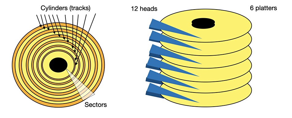
It is a 3D-coordinate system made out of a vertical coordinate head, a horizontal (or radial) coordinate cylinder, and an angular coordinate sector. Head selects a circular surface: a platter in the disk (and one of its two sides). Cylinder is a cylindrical intersection through the stack of platters in a disk, centered around the disk's spindle. Combined, cylinder and head intersect to a circular line, or more precisely: a circular strip of physical data blocks called track. Sector finally selects which data block in this track is to be addressed, as the track is subdivided into several equally-sized portions, each of which is an arc of (360/n) degrees, where n is the number of sectors in the track.
1 Cylinder:
- A cylinder is a collection of tracks that are at the same position on each platter in the disk stack.
- All the tracks that are at the same distance from the center are grouped into one cylinder.
- Tracks in the same cylinder are physically above or below each other on the disk platters.
2 Head:
- A head is the mechanism that reads data from and writes data to the disk.
- Each platter in a hard disk has two surfaces (top and bottom).
- The head is positioned over a track to read or write data.
3 Sector:
- A sector is the smallest addressable unit on a disk.
- It is a portion, and it stores a fixed amount of data (usually 512 bytes).
Addressing with CHS:
- Cylinder Number (C):
- Specifies the cylinder on the disk.
- Cylinders are numbered starting from 0.
- Head Number (H):
- Specifies the platter surface (head) from which data is read or written.
- Heads are numbered starting from 0.
- Sector Number (S):
- Specifies the sector within the stack.
- Sectors are numbered starting from 1.
Example:
Let's say we want to read data from Cylinder 0, Head 0, Sector 1.
- Cylinder Number (C) = 0
- Head Number (H) = 0
- Sector Number (S) = 1
This would be represented as CHS (0, 0, 1).
3 Read Disk
The BIOS Disk Services interrupt, int 0x13, provides a set of functions for disk operations. These functions include reading and writing sectors on the disk.
But there is other way as well if you don't want to use the interrupt, but that is complex which is using ATA/ATAPI (IDE) Direct Access.
3.1 Disk Read Function:
The disk read function is invoked by setting up the necessary parameters in CPU registers and then triggering interrupt 0x13. Here's a breakdown of the steps involved:
Registers used in Disk Operations:
- AH Register:
- For Disk Read: AH = 0x02
- For Disk Write: AH = 0x03
- AL Register:
- Number of sectors to read or write
- CH Register:
- Cylinder number
- CL Register:
- Starting sector number (bits 0-5)
- Sector number to write (bits 0-5)
- DH Register:
- Head number
- DL Register:
- Drive number
- ES:BX Registers:
- Buffer address for data transfer
Disk Read Operation (AH = 0x02):
mov ah, 0x02        ; AH = 02h (read sectors from disk)
mov al, 0x01        ; AL = number of sectors to read
mov ch, 0x00        ; CH = cylinder number
mov cl, 0x02        ; CL = starting sector number (sector 2)
mov dh, 0x00        ; DH = head number
mov dl, 0x80        ; DL = drive number (0x80 for first hard disk)
mov bx, 0x6000      ; ES:BX = buffer address where data will be read

int 0x13            ; BIOS interrupt for disk operations
For the Int 0x13, we have to tell below things:
- What disk do we want to read?
During the boot, the booting device number is stored indlregister. - CHS Address?
The next sector to boot sector has the,C=0, H=0, S=2 - How many sectors?
1 - Where do we load them?
0x7c00(origin) + 200hex(512 in dec, boot sector size) = 0x7e00
Disk Write Operation (AH = 0x03):
mov ah, 0x03        ; AH = 03h (write sectors to disk)
mov al, 0x01        ; AL = number of sectors to write
mov ch, 0x00        ; CH = cylinder number
mov cl, 0x02        ; CL = starting sector number (sector 2)
mov dh, 0x00        ; DH = head number
mov dl, 0x80        ; DL = drive number (0x80 for first hard disk)
mov bx, 0x6000      ; ES:BX = buffer address where data will be written from

int 0x13            ; BIOS interrupt for disk operations
Return Values:
- Carry Flag (CF):
- CF = 0: Success
- CF = 1: Error occurred
- AH Register:
- Error code (if CF = 1)
Error Handling:
If an error occurs during the disk operation, the Carry Flag (CF) is set, and an error code is returned in the AH register. Common error codes include:
- 0x00: No error
- 0x01: Invalid function in AH
- 0x02: Address mark not found
- 0x03: Disk write-protected
- 0x04: Sector not found
- 0x05: Reset failed
- 0x06: Disk changed
- 0x07: Drive parameter activity failed
- 0x08: DMA overrun
- 0x09: Data boundary error
- 0x0A: Bad sector detected
3.2 ATA/ATAPI (IDE) Direct Access
Directly accessing the disk using the ATA/ATAPI interface allows bypassing BIOS interrupts for disk operations.
ATA, also known as IDE (Integrated Drive Electronics), is a standard interface for connecting storage devices like hard drives and SSDs to a computer system. It uses a series of I/O ports to send commands and data between the CPU and the disk.
Key Components:
- I/O Ports: Specific addresses used to send commands and receive data.
- Primary Channel: Typically uses I/O ports
0x1F0to0x1F7and0x3F6for control. - Secondary Channel: Uses I/O ports
0x170to0x177and0x376for control.
- Primary Channel: Typically uses I/O ports
- ATA Commands: Instructions sent to the disk, such as read or write commands.
- Registers: Used for data transfer, command issuance, and status checking.
Steps to Read a Disk Using ATA:
- Select the Drive:
- Specify whether you are accessing the master or slave drive on the selected channel.
- Use the drive/head register at
0x1F6to select the drive. For the master drive, set the value to0xA0, and for the slave drive, set it to0xB0.
- Set Up the Registers:
- Configure the necessary registers to indicate the sector count, sector number, cylinder number, and head number for the data you want to read.
- Sector Count Register (
0x1F2): Number of sectors to read. - Sector Number Register (
0x1F3): Starting sector number (LBA). - Cylinder Low Register (
0x1F4): Low byte of the cylinder number. - Cylinder High Register (
0x1F5): High byte of the cylinder number.
- Sector Count Register (
- Configure the necessary registers to indicate the sector count, sector number, cylinder number, and head number for the data you want to read.
- Issue the Read Command:
- Send the read command to the command register.
- Command Register (
0x1F7): Send theREAD SECTORScommand (0x20 for PIO mode).
- Wait for the Disk to be Ready:
- Poll the status register to ensure the disk is ready to transfer data.
- Status Register (
0x1F7): Poll this register and check the BSY (busy) and DRQ (data request) bits.
- Read the Data:
- Transfer the data from the disk to memory via the data register.
- Data Register (
0x1F0): Read the data from this register.
Read Sector in BIOS
Let's write a bios program to reads the second sector from the boot disk and then prints the content of the first byte of the sector on the screen.
[org 0x7c00]
mov [BOOT_DISK], dl                ; Save boot disk number

; setting up the stack
xor ax, ax
mov es, ax
mov ds, ax
mov bp, 0x8000
mov sp, bp

mov bx, 0x7e00

; reading the disk
mov ah, 2                         ; AH = 2 (Read sectors from disk)
mov al, 1                         ; AL = number of sectors to read
mov ch, 0                         ; CH = cylinder number
mov dh, 0                         ; DH = head number
mov cl, 2                         ; CL = starting sector number (sector 2)
mov dl, [BOOT_DISK]               ; DL = boot disk number
int 0x13                          ; BIOS interrupt to read disk sectors

; printing what is in the next sector
mov ah, 0x0e                      ; AH = 0Eh (teletype output)
mov al, [0x7e00]                  ; AL = content of the first byte of the sector
int 0x10                          ; BIOS interrupt for video services
jmp $                             ; Infinite loop

BOOT_DISK: db 0                   ; Boot disk number

; magic padding
times 510-($-$$) db 0
dw 0xaa55

; filling the second sector (the one that will be read) with 'A's
times 512 db 'A'
Explanation:
Boot Disk Detection:
mov [BOOT_DISK], dl: Save the boot disk number in theBOOT_DISKvariable.
Setting up the Stack:
xor ax, ax: Clear AX register.mov es, ax: Set ES register to 0.mov ds, ax: Set DS register to 0.mov bp, 0x8000: Set BP register to 0x8000.mov sp, bp: Set SP register to the value of BP.
Reading the Disk:
mov bx, 0x7e00: Buffer Address, Pointed by ES:BX, ES = 0 and BX = 0x7e00, so buffer address = 0x7e00.mov ah, 2: Set AH register to 2 (Read sectors from disk).mov al, 1: Set AL register to 1 (number of sectors to read).mov ch, 0,mov dh, 0,mov cl, 2: Set cylinder, head, and sector numbers respectively.mov dl, [BOOT_DISK]: Set DL register to the boot disk number.int 0x13: BIOS interrupt to read disk sectors.
Printing the Content of the Next Sector:
mov ah, 0x0e: Set AH register to 0x0E (teletype output).mov al, [0x7e00]: Load AL register with the content of the first byte of the sector.int 0x10: BIOS interrupt for video services.
Infinite Loop:
jmp $: Jump to itself, creating an infinite loop.
Boot Signature:
dw 0xaa55: Boot signature marking the end of the boot sector.
Filling the Second Sector with 'A's:
times 512 db 'A': Fill the second sector (the one that will be read) with 'A's.
Write to Sector, and then Read it again
[org 0x7c00]

BUFFER_SIZE equ 512             ; Size of the buffer
BUFFER      equ 0x6000          ; Address of the buffer

; Save boot disk number
mov [BOOT_DISK], dl

; Setting up the stack
xor ax, ax
mov es, ax
mov ds, ax
mov bp, 0x8000
mov sp, bp

; Filling the buffer with 'B's
mov di, BUFFER                 ; Set DI to point to the buffer
mov cx, BUFFER_SIZE            ; Set CX to the size of the buffer
mov al, 'B'                    ; AL = 'B'
rep stosb                      ; Fill the buffer with 'B's

; Writing the buffer to the disk
mov ah, 3                      ; AH = 3 (Write sectors to disk)
mov al, 1                      ; AL = number of sectors to write
mov ch, 0                      ; CH = cylinder number
mov dh, 0                      ; DH = head number
mov cl, 3                      ; CL = starting sector number (sector 3)
mov dl, [BOOT_DISK]            ; DL = boot disk number
mov bx, BUFFER                 ; Set BX to point to the buffer
int 0x13                       ; BIOS interrupt to write disk sectors

; Reading the sector back into the buffer
mov ah, 2                      ; AH = 2 (Read sectors from disk)
mov al, 1                      ; AL = number of sectors to read
mov ch, 0                      ; CH = cylinder number
mov dh, 0                      ; DH = head number
mov cl, 3                      ; CL = starting sector number (sector 3)
mov dl, [BOOT_DISK]            ; DL = boot disk number
mov bx, BUFFER                 ; Set BX to point to the buffer
int 0x13                       ; BIOS interrupt to read disk sectors

; Printing the content of the buffer
mov si, BUFFER                 ; Set SI to point to the buffer
mov cx, BUFFER_SIZE            ; Set CX to the size of the buffer

print_loop:
    mov ah, 0x0e               ; AH = 0Eh (teletype output)
    lodsb                      ; Load byte from [SI] into AL and increment SI
    or al, al                  ; Check if AL is zero (end of string)
    jz print_done              ; If zero, jump to print_done
    int 0x10                   ; BIOS interrupt for video services
    jmp print_loop             ; Continue printing characters

print_done:
    jmp $                      ; Infinite loop

BOOT_DISK: db 0                ; Boot disk number

; Magic padding
times 510-($-$$) db 0
dw 0xaa55
References
https://stanislavs.org/helppc/int_13.html

Leave a comment
Your email address will not be published. Required fields are marked *