
1 What are Storage Device Interfaces?
Storage device interfaces serve as the communication channels (pathways or protocols) between storage drives (such as hard disk drives or solid-state drives) and the rest of the computer system. These interfaces facilitate the exchange of data between the computer system and storage media. Think of them as the “keys” that allow your computer to access and manage data stored on these drives. These interfaces determine how data flows between the storage medium and the system components.
Below are some common storage device interfaces:
2 Types of Storage Device Interfaces
2.1 SCSI (Skuzzy)
SCSI (Small Computer System Interface) is a set of standards for connecting and transferring data between computers and peripheral devices. It was first developed in the early 1980s and has undergone numerous revisions to enhance its performance and capabilities. SCSI is known for its versatility, high performance, and ability to support multiple devices on a single bus, making it a preferred choice in enterprise environments, servers, and high-performance workstations.
Parallel vs. Serial Communication:
- Parallel SCSI: Original SCSI implementations used parallel communication, where multiple bits of data are transmitted simultaneously across multiple wires. While effective, this method faced limitations with signal integrity and electromagnetic interference as data rates increased.
- Serial SCSI (SAS): Modern SCSI implementations, like SAS, use serial communication. This method transmits data one bit at a time over a single pair of wires, allowing for higher speeds and longer cable lengths without signal degradation.
- Description: SAS is a high-performance interface used primarily for connecting enterprise-level storage devices such as HDDs and SSDs in servers and data centers.
- Usage: Commonly used in high-performance computing environments and enterprise storage solutions.
- Characteristics: Offers higher data transfer rates and better reliability compared to SATA. Supports advanced features such as multipath and hot-swapping.
2.2 IDE (Integrated Drive Electronics) | ATA (Advanced Technology Attachment)
2.2.1 PATA
- It was one of the earliest and most significant standards introduced into PC hardware, which controls the flow of data between the processor and the hard disk.
The Integrated Drive Electronics (IDE) interface, also known as ATA (Advanced Technology Attachment), is a standard interface for connecting storage devices like hard drives and optical drives to a computer's motherboard. Developed in the mid-1980s, IDE was widely adopted due to its simplicity and cost-effectiveness.
The term PATA (Parallel ATA) was introduced after the advent of SATA to distinguish the older interface. It was the dominant interface for many years before being largely replaced by Serial ATA (SATA) in the early 2000s.
History
- 1986: The IDE interface was introduced by Western Digital and Compaq to simplify the connection between hard drives and the motherboard. The innovation was to integrate the controller into the drive itself, reducing the complexity and cost of the system.

Key Features:
- Integrated Controller:
- Early storage solutions required a separate controller card. IDE integrated this controller into the drive, simplifying the architecture.
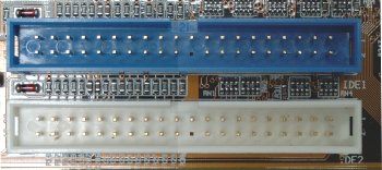
- 40/80 Pin Ribbon Cable:
- IDE uses a 40-pin ribbon cable for data transfer. An 80-pin version was introduced later to support higher data transfer rates, with the extra 40 pins used for grounding to reduce crosstalk.
- Master-Slave Configuration:
- Each IDE channel can support two devices: one configured as the master and the other as the slave. This is controlled via jumper settings on the drives.
- Data Transfer Modes:
- PIO (Programmed Input/Output): Data is transferred to and from the CPU. PIO modes 0 to 4 offer transfer rates from 3.3 MB/s to 16.6 MB/s.
- DMA (Direct Memory Access): Allows direct data transfer between the drive and system memory, bypassing the CPU for faster performance. Modes include Single-word DMA and Multi-word DMA.
2.2.2 SATA (Serial Advanced Technology Attachment):
- Description: SATA is a popular interface used for connecting internal storage devices such as HDDs and SSDs to the motherboard. It replaced the old Parallel ATA (PATA) interface and has become the standard for connecting mass storage devices to computers.
- Usage: Widely used in desktop computers, laptops, and servers for internal storage.
- Characteristics: Offers high-speed data transfer rates and hot-swappable support. SATA comes in different versions, including SATA I, SATA II, SATA III, with varying data transfer speeds.


Data Transmission:
- Serial Communication: SATA operates using a serial communication protocol, meaning data is transmitted sequentially over a single pair of wires.
- Unlike older parallel interfaces, SATA uses a single data path (one bit at a time) for transmitting information.
- Example: Imagine you want to transfer a file from your computer's SSD to the CPU. The file is broken down into packets of data, each transmitted serially through the SATA cable.
- This serial approach allows for faster and more efficient data transfer.
- Command Protocol:
- Command Structure: SATA uses a command-based protocol for communication between the host system (CPU) and the storage device. Commands are transmitted in a standardized format, including instructions for data transfer, error handling, and device management.
- Example: When the CPU sends a read command to the SSD, it includes parameters such as the starting address of the data to be read and the number of bytes to be transferred. The SSD processes the command and responds accordingly, transmitting the requested data back to the CPU.
- Control Signals:
- Transmission Control: SATA uses various control signals to manage data transmission, including transmit (TX) and receive (RX) signals, clock signals, and flow control mechanisms.
- Example: When data is being transmitted from the SSD to the CPU, control signals ensure that data is sent and received accurately and in the correct sequence.
- Error Handling:
- Error Correction: SATA incorporates error detection and correction mechanisms to ensure data integrity during transmission.
- Example: If a data transmission error occurs due to electrical noise or other factors, SATA devices use cyclic redundancy checks (CRC) to detect errors and retransmit the data if necessary. This helps ensure that data is transferred accurately between the storage device and the host system.
Data and Power Connectors:
- SATA devices connect through two ports: the data connector and the power connector.
- The data connector is a short, L-shaped seven-pin connector.
- The power connector is a taller 15-pin connector.
- The data cable transfers information, while the power cable supplies electricity to the drive.
Generations of SATA:
SATA has evolved over the years:
- SATA I (1.5 Gbps): Introduced in 2000.
- SATA II (3.0 Gbps): Revised in 2003.
- SATA III (6.0 Gbps): Commonly used today.
- Each generation increased speed and added features for faster and more reliable storage.
Use Cases:
SATA remains significant alongside newer standards like PCIe and NVMe.
It's ideal for:
- Larger HDDs: SATA is commonly used for traditional hard drives.
- Budget-Friendly SSDs: Entry-level SSDs often use SATA.
- Optical Drives: CD/DVD drives still rely on SATA.
Internal and External Connections:
- Internal SATA: Used within the computer case.
- Connects hard drives, SSDs, and optical drives to the motherboard.
- Common cable lengths: 305 mm, 457 mm, and 914 mm.
- External SATA (eSATA): Used for external devices.
- Connects to an eSATA port on the computer.
- Longer cables (914 mm or 1829 mm) for flexibility.
Advantages of SATA:
- Compatibility: Almost all PCs from the past decade use SATA.
- Reliability: Proven track record and widespread adoption.
- Cost-Effectiveness: Affordable for everyday storage needs.
Challenges:
- Speed Limitations: SATA III maxes out at 6 Gbps, limiting high-speed SSDs.
- Half-Duplex: Can’t read and write simultaneously.
- NVMe Competition: NVMe offers faster speeds for demanding workloads.
2.2.3 PATA Vs SATA
Serial ATA (SATA) and Parallel ATA (PATA) are both interfaces used for connecting storage devices like hard drives and optical drives to a computer's motherboard. However, they differ significantly in terms of technology, performance, and design.
- Data Transfer Method
- PATA (Parallel ATA):
- Parallel Communication: Transfers data using multiple parallel wires. A standard PATA cable has 40 wires (later 80 wires to reduce interference) that carry 16 bits of data simultaneously.
- Data Transfer Rates: Initial versions supported up to 16.6 MB/s, with later versions (Ultra ATA/133) reaching up to 133 MB/s.
- SATA (Serial ATA):
- Serial Communication: Transfers data serially using two pairs of wires, one for sending and one for receiving data, reducing interference and allowing for higher speeds.
- Data Transfer Rates: Initial versions supported 1.5 Gbps (150 MB/s), with SATA 3.0 reaching up to 6 Gbps (600 MB/s), and SATA 3.2 (SATA Express) supporting even higher speeds.
- PATA (Parallel ATA):
- Cables and Connectors
- PATA:
- Cable: Uses a wide 40-pin ribbon cable (80-wire for higher speeds) that is flat and cumbersome, making it difficult to manage and hindering airflow inside the case.
- Connector: Standard 40-pin connector for data and a separate 4-pin Molex connector for power.
- SATA:
- Cable: Uses a narrow 7-pin data cable, which is more flexible and easier to route, improving airflow within the computer case.
- Connector: Standard 7-pin data connector and a 15-pin power connector, allowing for a more compact design.
- PATA:
- Device Configuration
- PATA:
- Master-Slave Configuration: Each PATA channel supports two devices, one configured as master and the other as slave, using jumper settings on the drives.
- SATA:
- Point-to-Point Connection: Each SATA drive connects directly to the motherboard or controller without needing jumper settings. This simplifies installation and configuration.
- PATA:
- Hot Swapping
- PATA:
- No Hot Swapping: PATA drives do not support hot swapping, meaning drives cannot be added or removed while the computer is powered on.
- SATA:
- Hot Swapping Supported: SATA drives support hot swapping, allowing drives to be added or removed without shutting down the system (supported by the operating system and hardware).
- PATA:
- Advanced Features
- PATA:
- Limited Advanced Features: Basic support for features like DMA (Direct Memory Access) but lacks advanced functionalities.
- SATA:
- Advanced Features: Supports advanced features like Native Command Queuing (NCQ) for better multitasking performance, AHCI (Advanced Host Controller Interface) for enhanced capabilities, and power management features.
- PATA:
- Power Consumption
- PATA:
- Higher Power Consumption: The parallel interface typically consumes more power due to the larger number of wires and the need to drive signals over multiple lines simultaneously.
- SATA:
- Lower Power Consumption: The serial interface is more efficient, consuming less power and generating less heat, which is beneficial for energy savings and cooling.
- PATA:
- Physical Size and Design
- PATA:
- Larger Physical Size: The connectors and ribbon cables are bulkier, making them less suitable for compact or modern computer designs.
- SATA:
- Compact Design: Smaller connectors and thinner cables are more suitable for modern, compact, and high-density computer designs, such as in laptops and small form-factor desktops.
- PATA:
References:
2.3 AHCI
AHCI, or Advanced Host Controller Interface, is a technical standard defined by Intel that specifies the operation of Serial ATA (SATA) host controllers in a non-implementation-specific manner. It is designed to allow software to communicate with SATA devices such as hard drives and solid-state drives (SSDs).
What is AHCI?
AHCI stands for Advanced Host Controller Interface. It is a hardware mechanism that allows software to communicate with Serial ATA (SATA) devices. The specification provides a standard method for detecting, configuring, and programming SATA/AHCI adapters.
AHCI is not exactly the direct successor of ATA; rather, it complements and enhances the SATA (Serial ATA) interface, which itself is a successor to the older ATA (Advanced Technology Attachment) standards like PATA (Parallel ATA).
AHCI primarily changes how the motherboard and the system's software interact with SATA devices, rather than altering the physical connection itself.
Why AHCI?
AHCI was introduced to address several limitations of previous ATA standards and to fully leverage the capabilities of SATA devices. It provides several advanced features that improve the performance, efficiency, and functionality of storage devices.
Characteristics of AHCI
- Hot Plugging: AHCI supports hot swapping, which allows users to add and remove drives from the system without having to shut it down.
- Native Command Queuing (NCQ): This feature allows drives to optimize the order in which read and write commands are executed, improving overall performance especially in multitasking environments.
- Full SATA support: AHCI enables full utilization of SATA features, including higher data transfer speeds and more efficient data handling.
- Standardization: AHCI provides a standardized way to interface with SATA devices, making it easier for software developers to write compatible programs and drivers.
Note:
When SATA was first introduced, it included the inherent capability for hot swapping, but the lack of AHCI or equivalent controller interfaces meant that the system BIOS/UEFI and the operating system were not always capable of handling hot swaps smoothly. This could lead to issues such as data corruption or system instability if a drive was removed or added while the system was running.
Advantages of AHCI
- Improved Performance: Features like NCQ significantly enhance the performance of SATA drives by allowing more efficient command processing.
- Hot Swapping: The ability to add or remove drives without shutting down the system adds flexibility, particularly in enterprise and server environments.
- Compatibility and Interoperability: As a standardized interface, AHCI ensures that a wide range of software and operating systems can reliably interact with SATA devices.
- Enhanced Features: AHCI supports advanced SATA features such as staggered spin-up, port multipliers, and advanced power management.
Disadvantages of AHCI
- Legacy Support: Older operating systems and some legacy applications may not support AHCI natively, potentially leading to compatibility issues.
- Complexity: The advanced features of AHCI can add complexity to system setup and configuration, especially for users unfamiliar with the technology.
- Performance Overhead: In some cases, the additional processing required for features like NCQ can introduce slight overhead, potentially impacting performance in very specific scenarios.
- BIOS/UEFI Configuration: Switching from IDE to AHCI mode in BIOS/UEFI can sometimes require reinstalling the operating system or performing complex driver updates.
2.3 Peripheral Component Interconnect Express (PCIe):
- Description: PCIe is a high-speed serial interconnect used for connecting various components in a computer system, including storage devices.
- Usage: Widely used for connecting SSDs, expansion cards, graphics cards, and other high-bandwidth devices.
- Characteristics: Offers high bandwidth and low latency, making it suitable for high-performance storage solutions. PCIe SSDs can provide significantly faster data transfer rates compared to SATA-based SSDs.
2.4 Universal Serial Bus (USB):
- Description: USB is a standard interface used for connecting external storage devices such as flash drives, external HDDs, and SSDs to computers and other devices. It facilitates data transfer and power supply. USB is widely used due to its plug-and-play capability, hot-swappable support, and broad compatibility with various devices.
- Usage: Commonly used for portable storage solutions, data transfer, and peripheral connectivity.
- Characteristics: Offers plug-and-play functionality, compatibility with a wide range of devices, and hot-swappable support. USB comes in different versions, including USB 2.0, USB 3.0, USB 3.1, and USB 3.2, with varying data transfer speeds.
Cabling:
- USB cables consist of four or more wires: two for power (Vcc and Ground) and two for data transfer (Data+ and Data-).
- USB 3.x cables include additional wires for faster data transfer rates.
Data Transmission:
- Serial Communication:
- USB uses serial communication, meaning data is transmitted bit by bit over a single channel.
- Data is transferred in packets, each containing a header, payload, and error-checking information.
Protocol and Communication:
- Host-Centric Communication:
- The USB architecture is host-centric, meaning the host (usually a computer) initiates all communication.
- Devices respond to requests from the host. This ensures compatibility and simplifies device design.
- Device Classes:
- USB supports various device classes, such as Human Interface Devices (HID), Mass Storage, Audio, and Video.
- Each class follows specific protocols for communication and functionality.
- Polling and Interrupts:
- The host polls devices at regular intervals to check for data.
- Devices can also signal the host using interrupts when they need attention, such as when a key is pressed on a keyboard.
Power Delivery:
- Power Supply:
- USB provides power to connected devices, which can be useful for charging or powering peripherals.
- Standard USB 2.0 ports supply up to 500 mA at 5V, while USB 3.0/3.1 ports can supply up to 900 mA.
Plug-and-Play and Hot Swapping:
- Plug and Play:
- USB devices are automatically recognized and configured by the host operating system when connected.
- Drivers are either included in the OS or downloaded automatically.
- Hot Swapping:
- USB supports hot swapping, allowing devices to be connected or disconnected without powering down the computer.
- The host OS handles the dynamic changes in device availability.
Error Handling and Data Integrity
- Error Detection and Correction:
- USB uses cyclic redundancy check (CRC) for error detection in data packets.
- If an error is detected, the host requests retransmission of the data.
- Flow Control:
- USB manages data flow to prevent buffer overflow and ensure reliable data transfer.
Advanced Features:
- USB Hubs:
- USB hubs allow multiple devices to connect to a single USB port, expanding connectivity.
- Hubs can be powered or unpowered, with powered hubs providing additional power to connected devices.
- USB OTG (On-The-Go):
- USB OTG allows devices like smartphones and tablets to act as both a host and a peripheral.
- This enables direct communication between devices without a traditional host computer.
2.4 eSATA (External SATA):
- Description: eSATA is an external interface based on SATA technology, used for connecting external storage devices such as HDDs and SSDs to computers.
- Usage: Commonly used for high-speed external storage solutions, especially in desktop computers and workstations.
- Characteristics: Offers higher data transfer rates compared to USB, making it suitable for high-performance external storage solutions.
2.5 NVMe (Non-Volatile Memory Express)
Description: NVMe is a modern storage interface designed specifically for solid-state drives (SSDs) that use NAND flash memory.
Key Features:
- Low Latency: Offers significantly lower latency compared to traditional storage interfaces like SATA and SCSI.
- High Data Transfer Rates: Supports extremely high data transfer rates, maximizing SSD performance.
- Designed for Flash Memory: Optimized for NAND flash memory, providing improved efficiency and reliability.
- Direct CPU Access: Allows SSDs to communicate directly with the CPU, reducing overhead and improving performance.

Leave a comment
Your email address will not be published. Required fields are marked *