
In the previous chapter, we crafted a simple stage 1 flat binary bootloader, which is exactly 512 bytes in size (equivalent to one sector). This bootloader is loaded by the BIOS at memory location 0x7C00 and displays a welcome message on the screen. In this chapter we will enter in stage 2 land. The stage 2 would be in the same output format as of stage 1 which is flat binary (with no headers), it can be loaded and executed directly as soon as it is loaded by jumping to the starting memory address after it is loaded by the stage 1 bootloader.
In this chapter, we move one step further into the boot process by introducing Stage 2.
Stage 2 is:
- Still a flat binary (no ELF headers, no metadata)
- Loaded manual by Stage 1 using BIOS disk services
- Executed by a direct jump to its load address
- Much larger than Stage 1, allowing us to implement more complex boot logic.
This chapter lays the foundation for advanced bootloader.
1️⃣ Memory Map in Real Mode:
In real mode, the CPU behaves like an Intel 8086, exposing a 20-bit address bus which allows access to:
- 1 MB of memory
- Address range:
0x00000 - 0xFFFFF
20-bit Address Space:
- In real mode, the CPU has access to a
1 MB (1024 KB)address space (from 0x00000 to 0xFFFFF). - Addresses are formed by combining a segment and offset. The segment is shifted left by 4 bits (multiplied by 16), and the offset is added to it, giving a 20-bit physical address.
- Segment registers are 16-bit
- Offset registers are 16-bit
- Resulting physical address is 20-bit
- Maximum addressable memory:
1 MB (0x00000 - 0xFFFFF)
Segment:Offset Addressing
Memory address are formed using a segment:offset pair:
Physical Address = (Segment << 4) + Offset- Segment registers are 16-bit (CS, DS, ES, SS)
- Offset registers are 16-bit
- Resulting physical address is 20-bit
Example:
Segment:Offset → Physical Address
0x1234:0x5678 → (0x1234 << 4) + 0x5678
				= 0x12340 + 0x5678
				= 0x179B8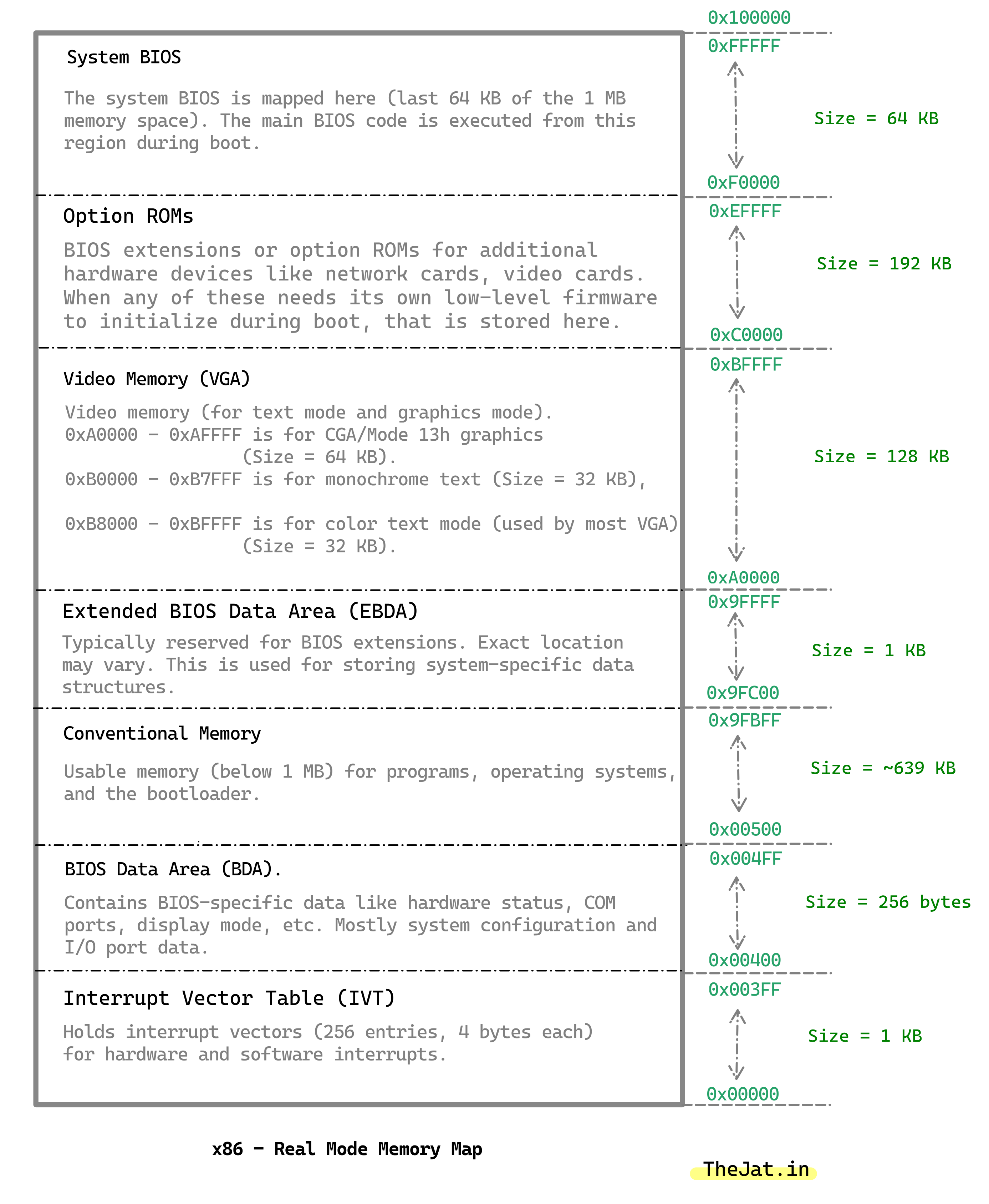
Here is the memory map for our bootloader:
; Memory Map:
; 0x00000000 - 0x000004FF		Reserved by BIOS
; 0x00000500 - 0x00007AFF		Second Stage Bootloader (~29 Kb)
; 0x00007B00 - 0x00007BFF		Stack Space (256 Bytes)
; 0x00007C00 - 0x00007DFF		Bootloader (512 Bytes)
; 0x00007E00 - 0x00008FFF		Used by subsystems in this bootloader
; 0x00009000 - 0x00009FFF		Memory Map
; 0x0000A000 - 0x0000AFFF		Vesa Mode Map / Controller Information
; 0x0000B000 - 0x0007FFFF		File Loading Area
Why load Stage at 0x0500?
- Below the Stage 1 bootloader
- Large contiguous free region
- Safe from BIOS data structures
- Easily reachable in real mode
Available memory:
0x7AFF - 0x0500 = 0x75FF = 30,207 bytes
						~ 29 KB
2️⃣ Things We will Do in this Chapter:
In this chapter, we will focus on developing the second stage of our bootloader. Our goal is to load a second stage file from the disk and transfer control to it. The second stage file will be loaded into memory and executed to further the boot process. We would use the BIOS function to load the stage 2 from the stage 1.
Our stage2 will be of size 29 KB (30207 bytes). Why?
Because we will be loading it to the location 0x0500 and we have 29 KB sized usable memory available here.
0x7AFF - 0x0500 = 0x75FF = 30207 Bytes = 29 KB.
We will pad the stage2 to be 29KB in exact, we will fill the extra space with zeroes using times instruction.
How we will read it and load it?
We will make use of BIOS functions to read from the disk image and load it at particular location. In the disk image our stage 1 would be at sector 1 and stage 2 starts from the sector 2 and spans up to sector 59.
Below is the layout of the disk image:
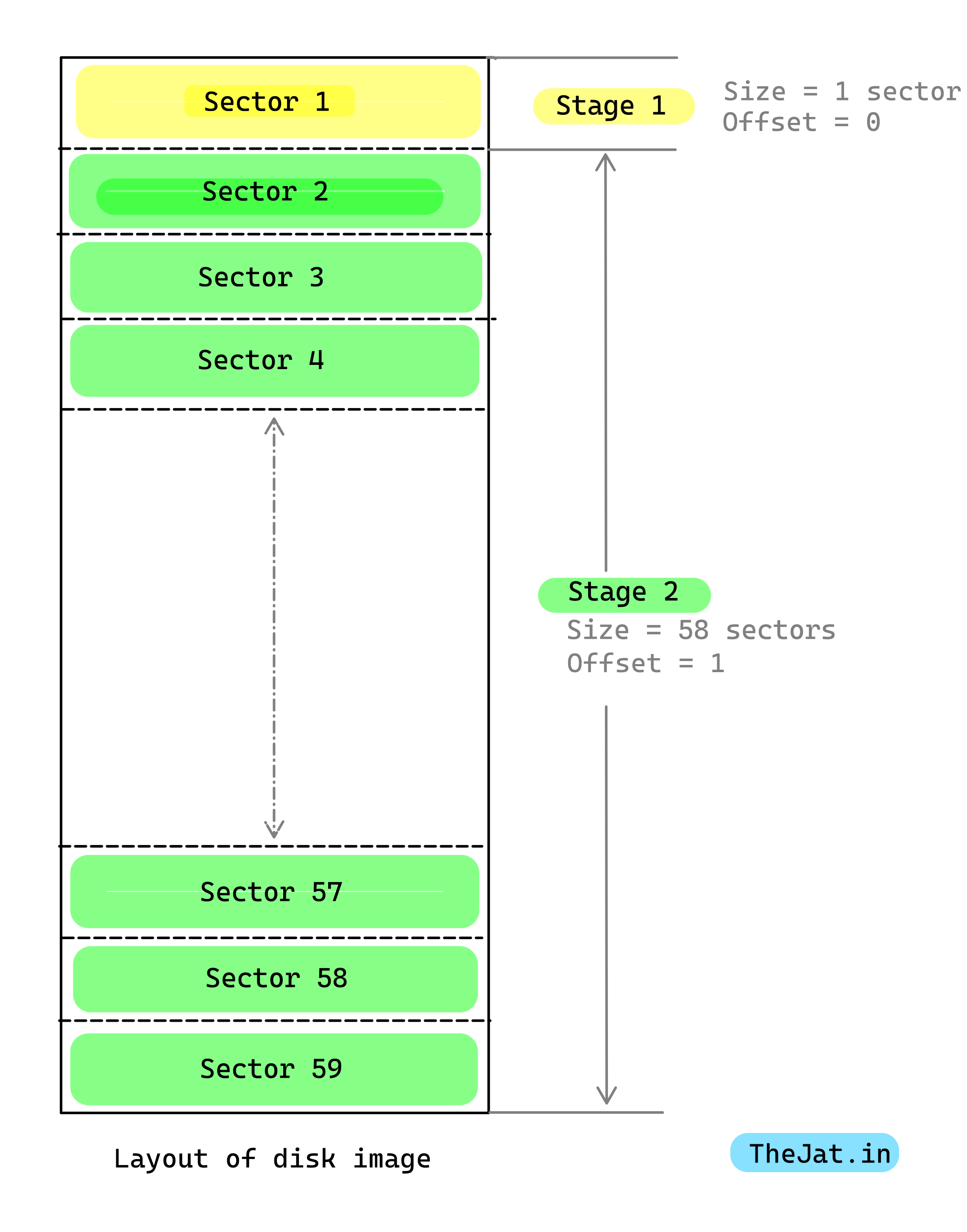
We use a raw disk image with the above layout:
| Sector | Content |
| 1 | Stage 1 Bootloader (512 bytes) |
| 2 - 59 | Stage 2 Bootloader (29 KB, 58 sectors) |
BIOS sector numbering starts at
1, while tools likedduse0-basedoffsets.
🪜 Steps-by-Steps Process:
Step 1: Writing the Stage 2 File
The stage 2 file will:
- Start in 16-bit mode.
- Be loaded at memory location
0x500 - Our stage 2 would be of size 29 KB.
- From
0x00000500to0x00007AFF - Will pad the extra data to make it complete 29 KB.
- From
- Print Welcome Message.
Step 2: Enhancing the Stage 1 File
We will enhance the stage 1 bootloader to:
- Load the stage 2 file from the disk (located at sector
2) using disk read BIOS function (Interrupt 0x13).- The stage 2 code starts at sector 2 and ends at the sector 58.
- Load the stage 2 file into memory location
0x500. - After successfully loading stage 2, it jumps to the address
0x500to transfer control to the stage 2 code. - In case of a disk read error, it halts the system in an infinite loop.

Step 3: Assemble the Stage 1 and Stage 2 Files
Assemble the both stages assembly files into flat binary format. By concatenating both binary into a single one.
Step 3: Writing to the Binary File into Disk Image
- Write the stage 1 to first sector of the disk.
- Write the stage 2 at the starting of the second sector and take up to
29KB * 1024 = 29,696 Bytes.- Start at sector
2. - Offset =
1. - Maximum Size of stage 2 could be:
29 KB = 29,696 Bytes.- Total disk sectors that it will cover = Size in Bytes / Size of 1 Sector in Bytes
29696 / 512 = 58 Sectors.
- Start at sector
3️⃣ Code Implementation:
3.1 Common Include Files to Both Stage 1 and Stage 2:
Common/defines.inc:
This file will consists of various variables and constants definition, which would be common to both stages:
%ifndef _COMMON_DEFINES_INC_
%define _COMMON_DEFINES_INC_

%define		STAGE_2_LOAD_ADDRESS	0x0500
%define		STAGE_2_SIZE			30207	; 0x7AFF - 0x500 = 0x75FF = 30,207
%define		STAGE_2_SECTORS_COUNT	STAGE_2_SIZE/512	; 30,207 / 512(size of 1 sector) = 58

%endifcommon/print16.inc:
This file contains the common displaying code in the real mode for both stage 1 and stage 2.
Functions:
ClearScreenAndResetCursor: Clears the screen and reset the cursor to (0, 0).PrintChar16BIOS: Prints the char on the screen using interrupt.- Input:
- AL = Character to print
- Input:
PrintString16BIOS: Prints the null terminated string on the screen using interrupt.- Input:
- SI = Null Terminated String
- Input:
PrintNumber: Prints the decimal value.- Input:
- EAX = Number to print
- Input:
SetTextColor: Set thebTextColorvariable which is used in the prints function.- Input:
- AL = Background color
- AH = Text color
- Example Usage:
- ; Set text color
mov al, BLACK
mov ah, GREEN
call SetTextColor
- ; Set text color
- Input:
%ifndef _COMMON_PRINT_16_INC_
%define _COMMON_PRINT_16_INC_

; 16 Bit Code
BITS 16

; Definitions
;;*********************************************
;; To be used by the SetTextColor Function
;; Example usage:->
;;; ; Set text color
;;; mov 	al, BLACK
;;;	mov 	ah, GREEN
;;;call 	SetTextColor

%define 		BLACK		0x0
%define 		BLUE 		0x1
%define 		GREEN 		0x2
%define 		CYAN 		0x3
%define 		RED 		0x4
%define 		MAGENTA 	0x5
%define 		BROWN 		0x6
%define 		LGRAY 		0x7
%define 		DGRAY		0x8
%define 		LBLUE		0x9
%define 		LGREEN		0xA
%define 		LCYAN		0xB
%define 		LRED		0xC
%define 		LMAGENTA	0xD
%define 		YELLOW		0xE
%define 		WHITE		0xF
;;*********************************************


; ********************************
; ClearScreenAndResetCursor
; This function clears the screen and resets the cursor at default (0,0) position

	pusha
	mov ah, 0x06		; BIOS Function: scroll up
	mov al, 0			; Number of lines to scroll (0 = clear entire screen)
	mov bh, 0x07		; Attribute for blank lines (light gray on black)
	mov cx, 0x0000		; CH = 0, CL = 0 (upper left corner)
	mov dx, 0x184F		; End at the bottom right (row 24, column 79)
	int 0x10			; Call BIOS interrupt

	; Reset cursor position to the top-left corner
	mov ah, 0x02		; BIOS function: Set cursor position
	mov bh, 0x00		; Page number (0)
	mov dh, 0x00		; Row (0)
	mov dl, 0x00		; Column (0)
	int 0x10			; Call BIOS interrupt

	popa
ret

; ********************************
; PrintChar16BIOS
; This function prints the char on the screen stored in AL register using the BIOS interrupts.
; IN:
; 	- AL: Char
; ********************************
PrintChar16BIOS:
	; Save the state of AX and BX registers
	push 	ax
	push 	bx

	; Setup for BIOS teletype output (INT 0x10, AH = 0x0E)
	mov 	ah, 0x0E               ; BIOS teletype function (TTY output)
	mov 	bl, byte [bTextColor]  ; Load the text color into BL
	mov 	bh, 0x00               ; Set the page number to 0 (usually not needed for TTY output)
	int 	0x10        ; BIOS video interrupt to print the character in AL

	; Restore the state of BX and AX registers
	pop 	bx
	pop 	ax
	ret            ; Return from the PrintChar16BIOS routine


; ********************************
; PrintString16BIOS

; This function prints the string referenced by the SI register using BIOS interrupts.
; IN:
; 	- SI: NULL-Terminated String
; ********************************
PrintString16BIOS
:
	; Save all general-purpose registers
	pushad

	; Loop to process each character in the string
	.cLoop16BIOS:
		; Load the next byte from the string (pointed to by SI) into AL
		lodsb

		; Check if the loaded byte is NULL (end of string)
		or	al, al
		jz	.PrintDone  ; If AL is zero, jump to the end of the print routine

		; Print the character in AL
		call PrintChar16BIOS
		jmp	.cLoop16BIOS  ; Repeat the loop for the next character

	.PrintDone:
		; \n
		; Move cursor to the beginning of the next line (equivalent of \n)
		mov ah, 0x02	; BIOS function: Set Cursor position
		inc dh			; Move cursor down to one line
		mov dl, 0x00	; MOve cursor to the beginning of the line (column 0)
		int 0x10		; Set cursor position to (DL, DH)

		; Restore all general-purpose registers
		popad
ret  ; Return from the PrintString16BIOS routine


; ********************************
; PrintNumber
; IN:
; 	- EAX: NumberToPrint
; ********************************
PrintNumber:
	; Save all general-purpose registers
	pushad

	; Initialize variables
	xor 	ebx, ebx        ; Clear EBX to use it as a counter for the number of digits
    mov 	ecx, 10         ; Set ECX to 10, the divisor for converting number to digits

	.DigitLoop:
	    xor 	edx, edx        ; Clear EDX before division
	    div 	ecx             ; Divide EAX by 10
	    ; After div: EAX contains quotient, EDX contains remainder

	    ; Convert remainder to ASCII
	    add 	edx, 48         ; Convert digit to ASCII ('0' = 48)

	    ; Store ASCII digit on the stack
	    push 	edx
	    inc 	ebx             ; Increment digit count

	    ; If quotient (EAX) is zero, we're done converting digits
	    cmp eax, 0
	    jnz .DigitLoop       ; If EAX is not zero, repeat the loop

	.PrintLoop:
		; Pop ASCII digit from stack into EAX
		pop 	eax

		; Print the character in EAX
		call 	PrintChar16BIOS

		; Decrease digit count in EBX
		dec 	ebx
		jnz 	.PrintLoop     ; If EBX is not zero, print next digit

    ; Restore all general-purpose registers
    popad
    ret                       ; Return from the PrintNumber routine


; ********************************
; SetTextColor
; IN:
; 	- AL: Background Color
;	- AH: Text Color
; ********************************
SetTextColor:
	; Save the state of AX and BX registers
	push 	ax
	push 	bx

	; Pack AH (Text Color) and AL (Background Color) into BL
	mov 	bl, ah          ; Move the text color (AH) into BL
	shl 	bl, 4           ; Shift BL left by 4 bits to make space for the background color
	and 	al, 0x0F        ; Ensure AL only contains the lower 4 bits (0-15) for the background color
	or 		bl, al          ; Combine BL (shifted text color) and AL (background color)

	; Store the combined color in bTextColor
	mov 	byte [bTextColor], bl

	; Restore the state of BX and AX registers
	pop 	bx
	pop 	ax
	ret          ; Return from the SetTextColor routine


; ********************************
; Variables
; ********************************

bTextColor	db	0x0F	; b - byte sized variable

%endifcommon/disk.inc:
This file consists the code for reading the disk.
ReadFromDisk: Read specified sector range data from the specified disk and load at the specified buffer. It uses Interrupt0x13.- Input:
- DL = Drive number
- CH = Cylinder number
- DH = Head number
- CL = Sector Number (starting sector 1 based)
- ES:BX = Memory address to load data to
- AL = Number of sectors to read
- Input:
Get more information of interrupt 0x13 disk reading function, here: https://thejat.in/learn/clear-screen-using-int-in-real-mode
%ifndef _COMMON_DISK_INC_
%define _COMMON_DISK_INC_

; 16 Bit Code
BITS 16

; ********************************
; ReadFromDisk
; IN:
; 	- DL: Drive number (0x00 = floppy A:, 0x80 = first HDD, etc.)
;	- CH: Cylinder number
;	- DH: Head number
;	- CL: Sector number (1-63)
;	- ES:BX: Memory address to load data to
;	- AL: Number of sectors to read
; ********************************
ReadFromDisk:
	; Save state
	pushad

	; Prepare for BIOS disk read
	mov 	ah, 0x02          ; BIOS function: Read sectors
	int 	0x13              ; Call BIOS disk interrupt

	; Check for errors
	jc 	.DiskReadError       ; If carry flag is set, jump to error handler

	; Restore state & return
	popad
	ret

.DiskReadError:
	; Handle disk read error (could be retry logic or error message)
	mov si, diskErrorMessage
	call PrintString16BIOS
	hlt
	jmp 	.DiskReadError

diskErrorMessage db 'Disk read error!`, 0

%endif
Explanation of Parameters:
DL: The drive number, such as0x00for the first floppy drive or0x80for the first hard disk.CH: The cylinder number on the disk.DH: The head number on the disk.CL: The sector number on the disk, which typically starts at 1.ES:BX: The memory segment and offset where the data will be loaded.AL: The number of sectors to read.
3.2 Modify boot/stage1/stage1.asm:
Now we need to modify the stage 1 code to read stage 2 from disk and load it to known memory address which will be 0x0500 and do the jump to this location.
; 16 Bit Code, Origin at 0x0
BITS 16
ORG 0x7C00
jmp main

; Includes
%include "boot/common/defines.inc"
%include "boot/common/print16.inc"	; For printing functions
%include "boot/common/disk.inc"		; For disk read function


main:
	; Disable Interrupts, unsafe passage
	cli

	; Far jump to fix segment registers
	jmp 	0x0:FixCS

FixCS:
	; Fix segment registers to 0
	xor ax, ax
	mov	ds, ax
	mov	es, ax

	; Set stack
	; The sp register is used to point to the top of the stack. By setting sp to 0x7C00, the bootloader ensures that the stack starts at the top of the memory allocated for the bootloader. This is important because the stack grows downward in memory, so it's set up before any other code runs.
	mov	ss, ax
	mov	ax, 0x7C00	; It ensure that there's space for the stack to grow downward without overlapping with other code or any other data in memory.
	mov	sp, ax

	; set interrupts
	sti

	; Save the DL register value, which contains the disk number
	mov 	byte [bPhysicalDriveNum], dl

	call ClearScreenAndResetCursor	; Clear the screen with light gray on black and reset the cursor

	;Print Welcome to the Screen
	mov si, WelcomeToStage1		; Load the address of the string into si register
	call PrintString16BIOS		; String printing function.

	; Load stage from the disk
	mov	dl, [bPhysicalDriveNum]	; Drive number
	mov ch, 0		; Cylinder number
	mov dh, 0		; Head number
	mov cl, 2		; Sector starting (1 Based Indexing, first sector is at index 1 which is boot sector)
	mov ax, 0x0000
	mov es, ax
	mov bx, STAGE_2_LOAD_ADDRESS	; Memory address (0x500)
	mov al, STAGE_2_SECTORS_COUNT	; 58 = Number of sectors to read
	call ReadFromDisk	; Call the routine to read from disk

	; Enter to Stage 2 land
	jmp STAGE_2_LOAD_ADDRESS

	; Infinite loop
	jmp $

; **************************
; Variables
; **************************
bPhysicalDriveNum	db	0	; Define variable to store disk number

WelcomeToStage1	db 'Welcome to the Stage1', 0	; Define welcome message

; Fill out bootloader
times 510-($-$$) db 0		; Fill up the remaining space with zeroes

; Boot Signature
db 0x55, 0xAA		; Boot signature indicating valid bootloader
3.3 Add stage 2 code:
stage2.asm:
As we discussed above that stage 1 will load our stage 2 at memory address 0x0500, so we need to set our stage 2 code origin to 0x500. Our stage 2 code as of now just prints the welcome message by using the print function which we have used in stage 1. For them we need to include common/print16.inc in our stage 2 file.
- Our stage 2 boot code will be 29 KB in size, as
0x0500 to 0x7AFFit is30207bytes (29 KB) long which is more than enough for our stage 2 bootloader for the time being. - So in the stage 1 we read 29 KB of data from the disk which are
30207 / 512=58sectors and loaded them at the starting of address0x0500. - You guys might be wondering isn't 29 KB is much much larger for our stage 2 code which just prints the welcome which should not take more than few bytes. Then what about the rest of space? We will pad them zero using the
timesinstruction.
BITS 16

%include "boot/common/defines.inc" ; For STAGE_2_LOAD_ADDRESS definition

ORG STAGE_2_LOAD_ADDRESS	; 0x500

; Memory Map:
; 0x00000000 - 0x000004FF		Reserved
; 0x00000500 - 0x00007AFF		Second Stage Bootloader (~29 Kb)
; 0x00007B00 - 0x00007BFF		Stack Space (256 Bytes)
; 0x00007C00 - 0x00007DFF		Bootloader (512 Bytes)
; 0x00007E00 - 0x00008FFF		Used by subsystems in this bootloader
; 0x00009000 - 0x00009FFF		Memory Map
; 0x0000A000 - 0x0000AFFF		Vesa Mode Map / Controller Information
; 0x0000B000 - 0x0007FFFF		File Loading Bay

jmp stage2_entry

; Includes
%include "boot/common/print16.inc"

stage2_entry:
	mov si, WelcomeToStage2
	call PrintString16BIOS

jmp $

; **********
; Variables
; **********

WelcomeToStage2 db 'Welcome to the Stage2', 0
times STAGE_2_SIZE - ($-$$) db 0		; Fill up the remaining space with zeroes
3.4 Makefile:
The makefile includes the recipe for the assembling, concatenating, and running the code.
# $@ = target file
# $< = first dependency
# $^ = all dependencies

BOOT_STAGE_INCLUDE = boot/common

all: build_dir boot run

build_dir:
	mkdir -p build

stage1.bin: boot/stage1/stage1.asm
	nasm -f bin -I $(BOOT_STAGE_INCLUDE) -o build/$@ $<

stage2.bin: boot/stage2/stage2.asm
	nasm -f bin -I $(BOOT_STAGE_INCLUDE) -o build/$@ $<

# concatenate the both stages of bootloader
boot: stage1.bin stage2.bin
	cat build/stage1.bin build/stage2.bin > build/boot.bin

# Optional creation of disk.img
disk.img:
	@echo "Creating the disk.img"
	# Create a blank 1.44MB disk image
	dd if=/dev/zero of=build/disk.img bs=512 count=2880

	# Write stage 1 bootloader to the first sector
	dd if=build/stage1.bin of=build/disk.img conv=notrunc

	# Write stage 2 bootloader to the sectors starting from the second sector
	dd if=build/stage2.bin of=build/disk.img bs=512 seek=2 conv=notrunc


run:
	qemu-system-x86_64 -drive  format=raw,file=build/boot.bin

# Clean up generated files
clean:
	rm -rf build
Explanation:
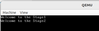
In QEMU we can run both the binary as well as disk image file. As of now we were running the flat binary file in QEMU.
We have a lot of ways to test our bootloader in QEMU.
First Method:
- Append stage 1 and stage 2 in single binary file. Use the appended flat binary file in QEMU, which is shown below:
cat build/stage1.bin build/stage2.bin > build/boot.bin
qemu-system-x86_64 -drive  format=raw,file=build/boot.bin
Second Method:
- Append stage 1 and stage 2 in single binary file. Then write the appended binary file to the disk image file and run that disk image file in the QEMU.
cat build/stage2.bin >> build/stage1.bin
# This command appends the contents of stage2.bin to stage1.bin
## OR
cat build/stage1.bin build/stage2.bin > build/boot.bin
# this one appends both the contents of stage1 and stage2 in new file boot.bin.

## Now write the generated appended boot.bin to disk.img file
# Create a blank 1.44MB disk image
dd if=/dev/zero of=build/disk.img bs=512 count=2880

# Write the combined bootloader to the first sectors of the disk image
dd if=build/boot.bin of=build/disk.img conv=notrunc
## OR
# if stage2 is appended to stage1 itself, not in new file.
dd if=build/stage1.bin of=build/disk.img conv=notrunc

## Test the Disk Image with QEMU
qemu-system-x86_64 -drive format=raw,file=build/disk.img
Third Method:
The third method is to write both stages of bootloader to disk image file individually.
# Create a blank 2MB disk image
dd if=/dev/zero of=build/disk.img bs=512 count=4096
# This creates a 2MB disk image file (4096*512 bytes = 2097152 bytes = 2048KB = 2MB)

# Write stage 1 bootloader to the first sector
dd if=build/stage1.bin of=build/disk.img count=1 conv=notrunc

# Write stage 2 bootloader to the sectors starting from the second sector
dd if=build/stage2.bin of=build/disk.img bs=512 seek=1 conv=notrunc- This makefile does the following:
- Creates a 1.44MB floppy disk image file filled with zeros.
- Writes the
stage1to the first 512 bytes ofdisk.img. - Then writes the
stage2.binto the second sector (starting at byte 512) ofdisk.img.
If in future, we are introducing stage 3 and writing it to the disk image file, just after the stage 2.
- Sector indexing on disk typically starts from
1when referring to the logical sectors of a track within a cylinder, especially in BIOS or disk addressing contexts. However, when working with tools likedd, the offset or sector counting starts from 0. - Since stage 2 is of size 29KB means
58sectors. It starts from sector 2 and end at the sector 59. - So our stage 3 will start from the sector 59.
dd if=/dev/zero of=disk.img bs=512 count=4096
dd if=stage1.bin of=disk.img bs=512 count=1 conv=notrunc
dd if=stage2.bin of=disk.img bs=512 seek=1 conv=notrunc
dd if=stage3.bin of=disk.img bs=512 seek=59 conv=notrunc- This code does the following:
- Creates a 2MB disk image file (4096 * 512 bytes).
- Writes
stage1.binto the first 512 bytes (Sector 0) ofdisk.img.- Contains the Stage 1 bootloader.
- Size: 512 bytes.
- Writes
stage2.binto the disk starting at Sector 1 (byte 512) to Sector 58 (byte 29,696).- Contains the Stage 2 bootloader.
- Total size: 29 KB (29 * 1024 bytes) = 29,696 bytes.
- Number of sectors: 29,696 bytes / 512 bytes per sector = 58 sectors
- Writes
stage3.binto the disk starting at Sector 59 (byte 30,208) to Sector 60 (byte 30,208).
3️⃣ Output
4️⃣ Repository
You can get this complete code with this commit: GitHub - The-Jat/TheTaaJ at a707d86de60d0ab1a942e4f92de5d12600313f16

Leave a comment
Your email address will not be published. Required fields are marked *