
Today we will write a minimalistic kernel and a stage 1 bootloader from scratch.
The stage1 bootloader will switch to 32 bit protected mode, Load the kernel at an offset mainly at 0x1000 and jump to it.
The kernel would be written in C and will just print a letter J on the screen using memory mapped frame buffer address.
The very first part of it is stage1boot.asm. It is explained below:
1 stage1boot.asm:
It will contain the MBR code which is loaded by the BIOS at memory location 0x7c00 and BIOS hands over control to it.
It should be of 512 bytes in size and should contain a valid boot signature.
- During the boot process, the BIOS reads the first sector of the boot device, which is known as the Master Boot Record (MBR) or boot sector. The MBR is a special section located at the beginning of a storage device (such as a hard drive or SSD) and contains the initial bootloader code.
- The BIOS reads this first sector (512 bytes) into memory and checks if it contains a valid MBR. The BIOS typically verifies the MBR's validity by checking for a specific signature, which is the last two bytes of the sector and is set to 0x55AA. If this signature is present, the BIOS considers the MBR valid.
- If the MBR is valid, the BIOS loads the bootloader code from the MBR into memory, usually starting at memory address 0x7C00 in real mode for x86 architecture. Once the bootloader is loaded into memory, the BIOS transfers control to the bootloader code by jumping to the memory address where the bootloader is loaded (0x7C00).
Steps done by stage1boot.asm:
1 Initialization:
- Set the origin point of the code to memory address
0x7c00. - Define a constant
KERNEL_OFFSETwith a value of0x1000, which is where the kernel will be loaded. - The boot disk number is saved in the
BOOT_DISKvariable. - Initialize the stack at memory address
0x8000.
2 Print Starting Real Mode String:
- We will print a string “Starting Real Mode" to indicate that we are in real mode for the time being.
3 Load Kernel:
- Our bootloader will then load the kernel from the boot disk into memory at the
KERNEL_OFFSET. - How would we get to know from which position in the disk to load the kernel and what could be the size of it?
4 Switch to Protected Mode:
- Then it will switch to the protected mode and jump to the protected environment able to use extended registers.
- To indicate this we will print a string onto the display saying “Switched to Protected Mode”.
5 Jump to Kernel
- As we all know our kernel has been loaded at memory address
KERNEL_OFFSET = 0x1000, Then we can just jump to this address, which will execute the kernel code.
6 Boot Signature
- At the last of this file, i.e the last two bytes of 512 bytes of code should be the boot signature.
- Which are
0x55and0xaa.
times (510-($-$$)) db 0
db 0x55
db 0xaa
or
times (510-($-$$)) db 0

dw 0xaa55   ; as x86 is little endian 55 would be at lower address and aa would be at higher address.
Code:
1 Initialization:
[org 0x7c00]        ; Set the origin point of the code to memory address 0x7C00

KERNEL_OFFSET equ 0x1000   ; Define the constant KERNEL_OFFSET with a value of 0x1000

; Stack initialization
mov [BOOT_DISK], dl    ; Save the boot disk number from the DL register to the memory location BOOT_DISK
mov bp, 0x8000         ; Set up the base pointer (BP) to 0x8000
mov sp, bp             ; Initialize the stack pointer (SP) to the value of the base pointer (BP)
Explanation:
[org 0x7c00]: This directive sets the origin point of the code to memory address 0x7C00. Bootloaders are typically loaded by the BIOS into this memory location.KERNEL_OFFSET equ 0x1000: This line defines a constant named KERNEL_OFFSET with a value of 0x1000. This constant is likely used to specify the memory location where the kernel will be loaded later in the code.mov [BOOT_DISK], dl: This instruction moves the value in the DL register, which typically holds the boot drive number, into the memory location identified by BOOT_DISK. This operation saves the boot disk number for later use.mov bp, 0x8000: This instruction initializes the base pointer (BP) register with the value 0x8000, setting up the stack segment base address.mov sp, bp: This instruction initializes the stack pointer (SP) register with the value of the base pointer (BP), effectively setting the initial stack pointer to the top of the stack, which is located at memory address 0x8000.
2 Print Starting Real Mode String:
MSG_REAL_MODE:
    db 'Starting real mode', 0

mov bx, MSG_REAL_MODE
print_string:
    pusha
    mov ah, 0x0e
print_string_cycle:
    cmp [bx], BYTE 0
    je print_string_end
    mov al, [bx]
    int 0x10
    add bx, 1
    jmp print_string_cycle
print_string_end:
    popa
Explanation:
MSG_REAL_MODE: This label marks the beginning of the message string 'Starting real mode'. The string is terminated with a null byte (0), which signifies the end of the string.mov bx, MSG_REAL_MODE: This instruction loads the address of the message string into the BX register, preparing it for printing.print_string: This label marks the beginning of the subroutine for printing a string.pusha: This instruction pushes all general-purpose registers (AX, CX, DX, BX, SP, BP, SI, DI) onto the stack. It's done to preserve their values during the subroutine execution.mov ah, 0x0e: This sets the AH register to 0x0E, which is the BIOS video output function.print_string_cycle: This label marks the beginning of the loop for printing each character of the string.cmp [bx], BYTE 0: This compares the byte at the memory address stored in BX with 0, checking if it's the null terminator signaling the end of the string.je print_string_end: If the byte is 0, the loop exits.mov al, [bx]: This moves the byte at the memory address stored in BX into the AL register, preparing it for printing.int 0x10: This BIOS interrupt call prints the character in AL register using the video output function.add bx, 1: This increments the BX register to move to the next byte of the message string.jmp print_string_cycle: This jumps back to the beginning of the loop to continue printing characters until the null terminator is encountered.print_string_end: This label marks the end of the subroutine. It restores all general-purpose registers from the stack usingpopa.
3 Load Kernel
disk_load:
    push dx              ; Save the DX register onto the stack
    mov ah, 0x02         ; Set AH register to 0x02, indicating the "Read Sectors From Drive" BIOS function
    mov al, dh           ; Set AL register to the number of sectors to read, which is stored in the DH register
    mov ch, 0x00         ; Set CH register to 0x00, indicating the cylinder number (for floppy disks)
    mov dh, 0x00         ; Set DH register to 0x00, indicating the head number (for floppy disks)
    mov cl, 0x02         ; Set CL register to 0x02, indicating the starting sector number (1-based)

    int 0x13             ; Call interrupt 0x13 to perform the disk read operation

    jc disk_error        ; If the carry flag (CF) is set (indicating an error), jump to disk_error

    pop dx               ; Restore the original value of DX register
    cmp al, dh           ; Compare AL (number of sectors read) with DH (number of sectors requested)
    jne disk_error       ; If they are not equal, jump to disk_error (indicating an error)

    ret                  ; Return from the subroutine

disk_error:
    mov bx, MSG_DISK_ERROR ; Load the address of the error message into the BX register
    call print_string      ; Call the print_string subroutine to print the error message
    jmp $                  ; Jump to the current location (infinite loop)

MSG_DISK_ERROR: db 'disk ERROR!', 0   ; Define the error message 'disk ERROR!', terminated with a null byte (0)

mov bx, KERNEL_OFFSET  ; Load the address where the kernel will be loaded into the BX register
mov dh, 1              ; Set DH register to 1, indicating the number of sectors to read
mov dl, [BOOT_DISK]    ; Load the boot disk number into the DL register
call disk_load         ; Call the disk_load subroutine to read the kernel from the disk
Explanation:
disk_load: This label marks the beginning of the subroutine responsible for loading sectors from the disk.push dx: This instruction pushes the value of the DX register onto the stack. It's done to preserve its value during the subroutine execution.mov ah, 0x02: This sets the AH register to 0x02, indicating the "Read Sectors From Drive" BIOS function.mov al, dh: This moves the value stored in the DH register (which typically holds the number of sectors to read) into the AL register, specifying the number of sectors to read.mov ch, 0x00: This sets the CH register to 0x00, indicating the cylinder number. This is typically used for floppy disks, but may not be relevant for all disk operations.mov dh, 0x00: This sets the DH register to 0x00, indicating the head number. Like CH, this is typically used for floppy disks.mov cl, 0x02: This sets the CL register to 0x02, indicating the starting sector number to read from (1-based).int 0x13: This BIOS interrupt call performs the disk read operation.jc disk_error: This checks if the carry flag (CF) is set, indicating an error occurred during the disk read operation. If so, it jumps to thedisk_errorlabel.pop dx: This restores the original value of the DX register.cmp al, dh: This compares the value stored in the AL register (number of sectors read) with the value stored in the DH register (number of sectors requested).jne disk_error: This jumps todisk_errorif the two values are not equal, indicating an error.ret: This instruction returns from the subroutine.disk_error: This label marks the beginning of the error handling routine.mov bx, MSG_DISK_ERROR: This loads the address of the error message into the BX register.call print_string: This calls theprint_stringsubroutine to print the error message.jmp $: This creates an infinite loop, causing the program to hang indefinitely at this point.MSG_DISK_ERROR: db 'disk ERROR!', 0: This defines the error message 'disk ERROR!', terminated with a null byte (0).
3 Switch to Protected Mode
[bits 16]
switch_to_pm:
    cli                    ; Turn off interrupts
    lgdt [gdt_descriptor] ; Load the Global Descriptor Table (GDT) descriptor
    mov eax, cr0          ; Move the value of the CR0 register into the EAX register
    or eax, 0x1           ; Set the least significant bit of EAX to 1 (to enable protected mode)
    mov cr0, eax          ; Move the modified value back to the CR0 register
    call CODE_SEG:init_pm ; Call the init_pm subroutine, defined below

[bits 32]
init_pm:
    mov ax, DATA_SEG      ; Move the value of DATA_SEG into the AX register
    mov ds, ax            ; Load the value of AX into the DS register (data segment)
    mov ss, ax            ; Load the value of AX into the SS register (stack segment)
    mov es, ax            ; Load the value of AX into the ES register (extra segment)
    mov fs, ax            ; Load the value of AX into the FS register
    mov gs, ax            ; Load the value of AX into the GS register

    mov ebp, 0x90000      ; Set up the stack pointer (ESP) to 0x90000
    mov esp, ebp          ; Load the value of EBP into ESP (stack pointer)

    call begin_pm         ; Call the begin_pm subroutine, defined below

gdt_begin:

gdt_null:
    dd 0x00               ; Null descriptor
    dd 0x00

gdt_code:
    dw 0xffff             ; Limit (16 bits)
    dw 0x0000             ; Base (16 bits)
    db 0x0                ; Base (24-31 bits)
    db 10011010b          ; Descriptor type and attributes (Code segment, non-conforming, readable, accessed)
    db 11001111b          ; Descriptor granularity and segment length (4KB, 32-bit, 16-bit code)
    db 0x0                ; Base (24-31 bits)

gdt_data:
    dw 0xffff             ; Limit (16 bits)
    dw 0x0000             ; Base (16 bits)
    db 0x0                ; Base (24-31 bits)
    db 10010010b          ; Descriptor type and attributes (Data segment, read/write, accessed)
    db 11001111b          ; Descriptor granularity and segment length (4KB, 32-bit)
    db 0x0                ; Base (24-31 bits)

gdt_end:

gdt_descriptor:
    dw gdt_end - gdt_begin - 1 ; GDT limit
    dd gdt_begin                ; GDT base

CODE_SEG equ gdt_code - gdt_begin ; Offset of the code segment in the GDT
DATA_SEG equ gdt_data - gdt_begin ; Offset of the data segment in the GDT

MSG_PROT_MODE:
    db 'Switched to protected mode', 0

[bits 32]

VIDEO_MEMORY equ 0xb8000   ; Define the starting address of VGA text mode memory
WHITE_ON_BLACK equ 0x0f    ; Define the attribute for white text on black background

print_string_pm:
    pusha                     ; Push all general-purpose registers onto the stack to preserve their values
    mov edx, VIDEO_MEMORY     ; Move the address of the start of video memory into the EDX register
print_string_pm_cycle:
    cmp [ebx], BYTE 0         ; Compare the byte at the memory address stored in EBX with 0 (null terminator)
    je print_string_pm_end    ; If it's 0, jump to the end of the subroutine

    mov ah, WHITE_ON_BLACK   ; Set the attribute for the text color
    mov al, [ebx]             ; Move the character at the memory address stored in EBX into AL register
    mov [edx], ax             ; Move the character and attribute to the video memory

    add ebx, 1                ; Move to the next character in the string
    add edx, 2                ; Move to the next character cell in the video memory (each cell is 2 bytes)

    jmp print_string_pm_cycle ; Repeat the loop to print the next character

print_string_pm_end:
    popa                       ; Restore the values of the general-purpose registers from the stack
    ret                        ; Return from the subroutine


begin_pm:
    mov ebx, MSG_PROT_MODE  ; Load the address of the message "Switched to prot mode" into the EBX register
    call print_string_pm    ; Call the print_string_pm subroutine to print the message
Explanation:
[bits 16]and[bits 32]: These directives indicate the current operating mode of the processor.[bits 16]denotes real mode, while[bits 32]denotes protected mode.cli: This instruction disables interrupts by clearing the interrupt flag (IF) in the FLAGS register.lgdt [gdt_descriptor]: This instruction loads the Global Descriptor Table (GDT) descriptor. The GDT contains descriptors for code segments, data segments, and other system segments used in protected mode.mov eax, cr0: This moves the value of the control register CR0 into the EAX register. CR0 contains various system control flags, including the flag that enables protected mode.or eax, 0x1: This sets the least significant bit of EAX to 1, enabling protected mode.mov cr0, eax: This moves the modified value of EAX back into the CR0 register, enabling protected mode.call CODE_SEG:init_pm: This calls the subroutineinit_pm, passing control to it to set up the data and stack segments and initialize the protected mode environment.init_pm: This subroutine sets up the data and stack segments for protected mode operation. It also initializes the stack pointer (ESP) to 0x90000.gdt_begin,gdt_null,gdt_code,gdt_data,gdt_end,gdt_descriptor: These labels and data define the Global Descriptor Table (GDT). The GDT contains segment descriptors that define the memory segments used in protected mode.CODE_SEGandDATA_SEG: These constants define the offsets of the code and data segments within the GDT. They are used to calculate the segment selectors used in protected mode.
print_string_pm:
VIDEO_MEMORY equ 0xb8000: This defines the starting address of the VGA text mode memory. In this mode, each character cell is represented by 2 bytes, where the first byte represents the ASCII character, and the second byte represents the color attribute.WHITE_ON_BLACK equ 0x0f: This defines the attribute for white text on a black background.print_string_pm: This label marks the beginning of the subroutine responsible for printing a string in protected mode.pusha: This instruction pushes all general-purpose registers (EAX, EBX, ECX, EDX, ESI, EDI, EBP, ESP) onto the stack to preserve their values.mov edx, VIDEO_MEMORY: This moves the address of the start of video memory into the EDX register.print_string_pm_cycle: This label marks the beginning of the loop for printing each character of the string.cmp [ebx], BYTE 0: This compares the byte at the memory address stored in EBX with 0 (null terminator) to check if the end of the string is reached.je print_string_pm_end: If the byte is 0, indicating the end of the string, the subroutine jumps toprint_string_pm_endto exit the loop.mov ah, WHITE_ON_BLACK: This sets the attribute for the text color to white on a black background.mov al, [ebx]: This moves the character at the memory address stored in EBX into the AL register.mov [edx], ax: This moves the character and its attribute (in AX register) to the video memory.add ebx, 1: This increments the EBX register to point to the next character in the string.add edx, 2: This moves the EDX register to the next character cell in the video memory (each cell is 2 bytes).jmp print_string_pm_cycle: This jumps back to the beginning of the loop to print the next character of the string.print_string_pm_end: This label marks the end of the subroutine. It restores the values of the general-purpose registers from the stack usingpopaand then returns from the subroutine usingret.
5 Jump to Kernel
call KERNEL_OFFSET  ; Call the subroutine located at the memory address specified by KERNEL_OFFSET
jmp $               ; Jump to the current location, creating an infinite loop
Explanation:
call KERNEL_OFFSET: This instruction calls the subroutine located at the memory address specified byKERNEL_OFFSET. It transfers control to the code starting at that memory location.jmp $: This instruction jumps to the current location.$typically represents the current instruction pointer. Since it's followed by nothing, this effectively creates an infinite loop, causing the program execution to stay at this point indefinitely.
2 kernel.c:
void k_main() {
    char* video_memory = (char*)0xb8000;  // Declare a pointer to the VGA text mode memory address

    // Define the character and attribute bytes
    char character = 'J';
    char attribute = 0x0F;  // This attribute byte represents white text on a black background

    // Combine the character and attribute bytes and write to memory
    *video_memory = character;
    *(video_memory + 1) = attribute;  // The attribute byte follows the character byte in memory
}
Explanation:
void k_main(): This is a kernel entry point function namedk_main().char* video_memory = (char*)0xb8000;: This declares a pointervideo_memoryand initializes it with the address0xb8000, which represents the start of VGA text mode memory. In VGA text mode, each character cell is represented by two bytes: one for the character itself and one for its attribute (such as color).char character = 'J';: This defines the character to be displayed. In this case, it's the letter 'J'.char attribute = 0x0F;: This defines the attribute byte. In VGA text mode, the attribute byte typically consists of foreground and background color information. Here,0x0Frepresents white text on a black background.*video_memory = character;: This writes the character to the memory location pointed to byvideo_memory.*(video_memory + 1) = attribute;: This writes the attribute byte to the memory location immediately following the character byte. In VGA text mode, the character byte and the attribute byte are stored consecutively for each cell.
3 Compilation & Linking
We have now two files, one is our stage1boot.asm - the main entry point of the booting while other is kernel.c the entry point of the kernel.
First we have to compile them and later link them:
1 Assembling the stage1 bootloader:
nasm -f bin stage1boot.asm -o stage1boot.binnasm: This is the NASM assembler.-f bin: This option specifies the output format of the assembled code. In this case, it specifies that the output should be in binary format.stage1boot.asm: This is the input assembly file that NASM will assemble.-o stage1boot.bin: This option specifies the output file name. The-oflag is followed by the desired output file name, which in this case isstage1boot.bin.- The output should be of 512 bytes so that it can be fit into the boot sector.
2 Compiling the kernel.c:
gcc -m32 -ffreestanding -fno-pie -c kernel.c -o kernel.ogcc: This is the GNU Compiler Collection, specifically the C compiler.-ffreestanding: This option tells GCC to compile the code for a "freestanding" environment, which means the resulting binary does not rely on a standard library or operating system. This is typically used for writing code that runs directly on hardware, such as operating system kernels.-c: This option instructs GCC to generate an object file (.o) from the source file, but not to perform linking. It compiles the source code into machine code and stores it in an object file without creating an executable.kernel.c: This is the input C source file that GCC will compile.-o kernel.o: This option specifies the output file name. The-oflag is followed by the desired output file name, which in this case iskernel.o.
We got our binary files each for every source files. Now we need to link them together to make a combined binary file which we can use to test our dummy OS.
We would need a separate entry point that will be in assembly which will be loaded at KERNEL_OFFSET location and will call the k_main() function. For that we would need two things:
- kernel_entry.asm
- Linker.ld
3 kernel_entry.asm:
[bits 32]          ; Assemble in 32-bit mode

[extern k_main]    ; Declare that the symbol k_main is defined in another file

start:             ; Label marking the entry point of the program
    call k_main    ; Call the external k_main function
    jmp $          ; Infinite loop: jump to the current instruction, effectively halting further execution
Explanation:
1 [bits 32]
; Assemble in 32-bit mode: This directive tells the assembler to generate 32-bit code, which is appropriate for the i386 architecture.
2 [extern k_main]
; Declare that the symbol k_main is defined in another file: This indicates thatk_mainis an external function. It will be linked later from another object file or module.
3 start:
; Label marking the entry point of the program: Thestartlabel serves as a marker for the program's entry point. The linker script sets this as the entry point.
4 call k_main
; Call the external k_main function: This instruction calls the functionk_main. Execution jumps tok_main, and whenk_maincompletes, execution returns to the next instruction aftercall.
5 jmp $
; Infinite loop: jump to the current instruction, effectively halting further execution: This creates an infinite loop by jumping to the instruction at the current address ($). This prevents the CPU from executing any unintended code afterk_mainreturns.
4 linker.ld:
OUTPUT_FORMAT(elf32-i386)
ENTRY(start)
SECTIONS
{
	. = 0x1000;
	.text : {
		*(.text)
	}

	.rodata : {
		*(.rodata)
	}

	.data : {
		*(.data)
	}

	.bss : {
		*(.bss)
	}
}
Explanation:
1 OUTPUT_FORMAT(elf32-i386)
- This line specifies the output file format of the linked executable. "elf32-i386" indicates that the executable will be in the ELF (Executable and Linkable Format) format for a 32-bit x86 (i386) architecture. ELF is a common file format for executables, object code, shared libraries, and core dumps.
2 ENTRY(start)
- This line sets the entry point of the program to a symbol named
start. The entry point is where the program begins execution. Thestartsymbol is typically defined in the program's startup code or assembly file.
3 SECTIONS
- The
SECTIONScommand is used to define how different sections of the input object files are mapped into the output file. This command is the core of the linker script, detailing the layout of the executable in memory.
4 Memory Address Setting
. = 0x1000;- This line sets the current memory location counter to
0x1000. This means the following section, which is.textin this case, will start at memory address0x1000.
- This line sets the current memory location counter to
5 .text Section
.text : { *(.text) }- This section definition specifies that all input sections named
.textfrom the object files should be collected and placed into the output section named.text. The.textsection typically contains the executable code (functions and instructions).
- This section definition specifies that all input sections named
6 .rodata Section
.rodata : { *(.rodata) }- Similar to the
.textsection, this line specifies that all input sections named.rodatashould be placed into the output section named.rodata. The.rodatasection usually contains read-only data such as string literals and constants that should not be modified at runtime.
- Similar to the
7 .data Section
.data : { *(.data) }- This line specifies that all input sections named
.datashould be placed into the output section named.data. The.datasection typically contains initialized global and static variables that can be modified at runtime.
- This line specifies that all input sections named
8 .bss Section
.bss : { *(.bss) }- This line specifies that all input sections named
.bssshould be placed into the output section named.bss. The.bsssection usually contains uninitialized global and static variables. At runtime, these variables are zero-initialized by the program loader.
- This line specifies that all input sections named
6 Assembling kernel_entry.asm
nasm kernel_entry.asm -f elf32 -o kernel_entry.o- nasm: This is the NASM (Netwide Assembler) command used to assemble assembly language source files.
- kernel_entry.asm: This is the name of the assembly source file to be assembled. It's assumed that the file is named "kernel_entry.asm" or similar.
- -f elf32: This option specifies the output format of the assembled code. In this case, it's set to "elf32", indicating that the output should be in the ELF (Executable and Linkable Format) format for 32-bit systems.
- -o kernel_entry.o: This option specifies the output file name. In this case, the assembled object code will be saved as "kernel_entry.o".
7 Linking:
ld -m elf_i386 -o kernel.bin -T linker.ld kernel_entry.o kernel.o --oformat binary- ld: This is the GNU linker command used to link object files and libraries to create an executable or binary file.
- -m elf_i386: This option specifies the target architecture for the output file. In this case, it's set to "elf_i386", indicating that the output should be compatible with the 32-bit x86 architecture in ELF format.
- -o kernel.bin: This option specifies the output file name. In this case, the linked binary file will be named "kernel.bin".
- -T linker.ld: This option specifies the linker script to use for controlling the linking process. In this case, it's set to "linker.ld".
- kernel_entry.o kernel.o: These are the input object files that contain the compiled code to be linked together. "kernel_entry.o" likely contains the entry point code, while "kernel.o" contains the kernel code itself.
- --oformat binary: This option specifies the output file format. In this case, it's set to "binary", indicating that the output should be a raw binary file rather than an ELF executable.
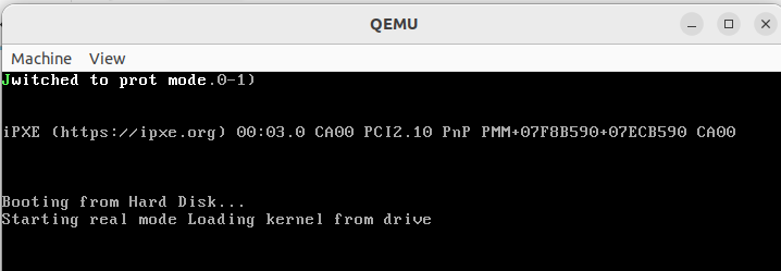
4 Output
5 References
Full Source Code:
https://github.com/The-Jat/TheBareMetal/tree/main/Minimalistic_C_Kernel
https://github.com/opuntiaOS-Project/opuntiaOS/tree/b945a850fc6f96f5dead731ddcc60567b0195d5e

Leave a comment
Your email address will not be published. Required fields are marked *