When building a multi-stage bootloader, passing information from Stage 1 to Stage 2 is a fundamental requirement. Stage 1 is extremely small (512 bytes), BIOS-loaded, and hardware facing, while Stage 2 is larger and more flexible. To coordinate correctly, Stage 1 must convey essential data to Stage 2 in a reliable and deterministic way.
Passing data from Stage 1 to Stage 2 in a bootloader involves storing necessary information in a way that Stage 2 can easily access and utilize. This data might include memory maps, boot device information, and any parameters needed to locate and load the Stage 2 bootloader.
Typical data passed between stages includes:
- Boot device number (BIOS drive number)
- Memory layout information
- Disk layout
- Flags or mode indicators
- Temporary parameters used during early boot
This chapter explains all practical and real-world methods to pass data between bootloader stages, with working examples, trade-offs, and best practices, using TheTaaJ bootloader architecture as reference.
🔰 Methods for Passing Data
- Using a Fixed Memory Location
- Using CPU Registers
- Using Stack
- Using BIOS Data Area
- Using Disk Storage
- Using a Data Structure in Memory
| Method | Suitable for | Complexity | Reliability |
| Fixed Memory Location | Very-medium data | Low | High |
| CPU Registers | Very small data | Very Low | Medium |
| Stack | Small ordered data | Medium | Medium |
| BIOS Data Area (BDA) | BIOS-related info | Medium | Medium |
| Disk Storage | Large / persistent data | High | High |
| Structured Memory Block | Complex boot params | Medium-High | Very High |
1️⃣ Using a Fixed Known Memory Location
One common method is to use a predefined memory location to store data. This memory location must be agreed upon by both Stage 1 and Stage 2. This method ensures that data remains persistent between stage transitions as long as the memory region is not overwritten.
✧ Steps:
1 Choose a Memory Location:
Decide on a specific memory location where both stage 1 and stage 2 can access the data. This could be in the bootloader segment (such as where the bootloader loads the kernel) or a known location in memory that both stages agree upon.
2 Store Data in Stage 1:
In stage 1 (e.g., bootloader), store the data you want to pass in a designated memory location. This could be done using mov instructions to write data directly to a specific memory address or by storing it in a predefined data section of your bootloader code.
; Stage 1: Store data at a fixed memory location (e.g., 0x9000:0x0000)
org 0x7C00

start:
    ; Example data to pass (e.g., disk number 0x80)
    mov byte [0x9000:0x0000], 0x80

    ; Load Stage 2 bootloader
    ; (Assume stage2.bin starts at 0x7E00)
    mov ax, 0x07E0
    mov es, ax
    mov bx, 0x0000
    ; Load 512 bytes from disk (code to load sector omitted for brevity)
    ; ...

    ; Jump to Stage 2
    jmp 0x07E0:0000

times 510-($-$$) db 0
dw 0xAA55
3 Load Data in Stage 2:
In stage 2, load the data from the same memory location where stage 1 stored it.
; Stage 2: Read data from the fixed memory location
org 0x7E00

start:
    ; Read the data passed by Stage 1
    mov al, [0x9000:0x0000]

    ; Now AL contains the disk number 0x80 passed by Stage 1
    ; Use the data as needed
    ; ...

    ; Halt the CPU
    hlt

times 512-($-$$) db 0
Considerations:
- Memory Safety: Ensure that the memory location chosen is safe and does not overwrite critical bootloader or kernel code.
- Alignment: Pay attention to memory alignment and access rules, especially in real mode or when dealing with low-level programming environments.
- Memory alignment means placing data at memory addresses that are multiples of the data size. For example:
- A 2-byte value (like a
word) should be stored at an even address. - A 4-byte value (like a
dword) should be stored at an address divisible by 4. - An 8-byte value (like a
qword) should be stored at an address divisible by 8.
- A 2-byte value (like a
- Memory alignment means placing data at memory addresses that are multiples of the data size. For example:
Complete Example through the TheTaaJ Code:
stage1.asm:
; 16 Bit Code, Origin at 0x0
BITS 16
ORG 0x7C00
jmp main
; Includes
%include "boot/common/defines.inc" ; For constants and common variables
%include "boot/common/print16.inc" ; For printing functions
%include "boot/common/disk.inc" ; For disk read function
main:
; Disable Interrupts, unsafe passage
cli
; Far jump to fix segment registers
jmp 0x0:FixCS
FixCS:
; Fix segment registers to 0
xor ax, ax
mov ds, ax
mov es, ax
; Set stack
; The sp register is used to point to the top of the stack. By setting sp to 0x7C00, the bootloader ensures that the stack starts at the top of the memory allocated for the bootloader. This is important because the stack grows downward in memory, so it's set up before any other code runs.
mov ss, ax
mov ax, 0x7C00 ; It ensure that there's space for the stack to grow downward without overlapping with other code or any other data in memory.
mov sp, ax
; set interrupts
sti
; Save the DL register value, which contains the disk number
mov byte [bPhysicalDriveNum], dl
call ClearScreenAndResetCursor ; Clear the screen and reset the cursor
;;;;;;;;;;;;;;;;;;;;;;;;;;;;;;;;;;;;;;;;;;;;;
;; Debugging Purpose
;;;;;;;;;;;;;;;;;;;;;;;;;;;;;;;;;;;;;;;;;;;;;
;; Print the Register value in hex and decimal
; mov ax, 1234
; mov dx, ax
; call PrintWordHex ; Print dx value in hex
; call PrintNewline ; \n
; call PrintWordNumber ; Print ax value in number
; call PrintNewline ; \n
;Print Welcome to the Screen
mov si, WelcomeToStage1 ; Load the address of the string into si register
call PrintString16BIOS ; String printing function.
call PrintNewline ; \n
; Load stage from the disk
mov dl, [bPhysicalDriveNum] ; Drive number
mov ch, 0 ; Cylinder number
mov dh, 0 ; Head number
mov cl, 2 ; Sector starting (Indexed 1, as first sector is at index 1)
mov ax, 0x0000
mov es, ax
mov bx, STAGE_2_LOAD_ADDRESS ; Memory address (0x500)
mov al, STAGE_2_SECTORS_COUNT ; 58 Number of sectors to read
call ReadFromDisk ; Call the routine to read from disk
;;;;;;;;;;;;;;;;;;;;;;;;;;;;;;;;;;;;;;;;;;;;;;;;;;;
;; Pass Data from stage 1 to stage 2,
;; through register
; mov ax, 77
; Call PrintWordNumber
; call PrintNewline ; \n
;;;;;;;;;;;;;;;;;;;;;;;;;;;;;;;;;;;;;;;;;;;;;;;;;;;
;;;;;;;;;;;;;;;;;;;;;;;;;;;;;;;;;;;;;;;;;;;;;;;;;;;
;; Pass Data from stage 1 to stage 2,
;; through known fixed memory location
;; For our example, we will pass the data by storing
;; at memory "0x7E00" which is just after the bootcode.
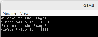
mov ax, 1628
mov word [0x7E00], ax ; Store the passing value at the location,
; by specifying size explicitly.
;; OR
;; mov [0x7E00], ax ; Store the passing value at the location
; Without specifying size explicitly, the assembler
; interprets it as to store the data of size of AX
; which is word size.
;; These both methods works, as AX is of word size,
;; so assembler only stores word size data at the location.
Call PrintWordNumber ; Print the Passing data
Call PrintNewline ; \n
;;;;;;;;;;;;;;;;;;;;;;;;;;;;;;;;;;;;;;;;;;;;;;;;;;;
; jump to the stage 2 land
jmp STAGE_2_LOAD_ADDRESS ; 0x0500
; Infinite loop
jmp $
; **************************
; Variables
; **************************
bPhysicalDriveNum db 0 ; Define variable to store disk number
WelcomeToStage1 db 'Welcome to the Stage1', 0 ; Define welcome message
; Fill out bootloader
times 510-($-$$) db 0 ; Fill up the remaining space with zeroes
; Boot Signature
db 0x55, 0xAA ; Boot signature indicating valid bootloader- In this stage 1 code, we are passing the data at known memory location.
- The known memory location is
0x7E00which is free to use and it is immediately after the boot code. - The passed value is
1628
stage2.asm:
BITS 16

%include "boot/common/defines.inc" ; contains defintion for STAGE_2_LOAD_ADDRESS

ORG STAGE_2_LOAD_ADDRESS	; 0x0500

; Memory Map:
; 0x00000000 - 0x000004FF		Reserved
; 0x00000500 - 0x00007AFF		Second Stage Bootloader (~29 Kb)
; 0x00007B00 - 0x00007BFF		Stack Space (256 Bytes)
; 0x00007C00 - 0x00007DFF		Bootloader (512 Bytes)
; 0x00007E00 - 0x00008FFF		Used by subsystems in this bootloader
; 0x00009000 - 0x00009FFF		Memory Map
; 0x0000A000 - 0x0000AFFF		Vesa Mode Map / Controller Information
; 0x0000B000 - 0x0007FFFF		File Loading Bay

jmp stage2_entry

; Includes
%include "boot/common/print16.inc"

stage2_entry:
	mov si, WelcomeToStage2		; Print Stage 2 Welcome message
	call PrintString16BIOS
	call PrintNewline		; \n

	;;;;;;;;;;;;;;;;;;;;;;;;;;;;;;;;;;;;;;;;;;;;;;;;;;;
	;; Receive Register Passed Value from Stage 1
	;; Stage 1 Passed the value in AX
	; call PrintWordNumber		; Print the Received AX value
	; call PrintNewline		; \n
	;;;;;;;;;;;;;;;;;;;;;;;;;;;;;;;;;;;;;;;;;;;;;;;;;;;


	;;;;;;;;;;;;;;;;;;;;;;;;;;;;;;;;;;;;;;;;;;;;;;;;;;;
	;; Receive the Fixed Known Memory Location Passed value from Stage 1
	;; In our case the known memory location is "0x7E00"
	;; and passed data is of 16 bit.
	mov ax, [0x7E00]		; Read word size data from the location, without
					; specifying size explicitly, assembler treats it as
					; to read data of size of AX from the location which
					; is of word size.
	;; OR,
	; mov word ax, [0x7E00]		; Read word size data from the location by,
					; specifying size explicitly.

	call PrintWordNumber		; Print the received data
	call PrintNewline		; \n
	;;;;;;;;;;;;;;;;;;;;;;;;;;;;;;;;;;;;;;;;;;;;;;;;;;;

jmp $

; **********
; Variables
; **********

WelcomeToStage2 db 'Welcome to the Stage2', 0
times STAGE_2_SIZE - ($-$$) db 0 ; Fill up the remaining space with zeroes- Here in this
stage2code, we know that stage 1 has sent us data at memory location0x7E00. - We just read a word long data from that location and printed it.
- The received value should be
1628. - Below is the output of the code.
- Complete Code at: https://github.com/The-Jat/TheTaaJ/tree/57466fe64fc90ccb7d145aba6fb488701feab185
Pros:
- Simple and straightforward.
- Persistent storage until explicitly overwritten.
Cons:
- Fixed memory locations may conflict with other parts of the system.
- Limited flexibility.
2️⃣ Using CPU Registers
Another method is to use CPU registers to pass data. This method is limited by the number of available registers but can be straightforward for small amounts of data. This method is fast and direct, suitable for small amounts of data.
Stage 1: Passing Data
; Stage 1: Pass data via CPU registers
org 0x7C00

start:

    ; Load Stage 2 bootloader
    ; (Assume stage2.bin starts at 0x7E00)
    mov ax, 0x07E0
    mov es, ax
    mov bx, 0x0000
    ; Load 512 bytes from disk (code to load sector omitted for brevity)
    ; ...
	mov dl, 0x80 ; Example data to pass (e.g., disk number 0x80 in DL)
    ; Jump to Stage 2
    jmp 0x07E0:0000

times 510-($-$$) db 0
dw 0xAA55
Stage 2: Receiving Data
; Stage 2: Read data from CPU registers
org 0x7E00

start:
    ; Read the data passed by Stage 1
    mov al, dl

    ; Now AL contains the disk number 0x80 passed by Stage 1
    ; Use the data as needed
    ; ...

    ; Halt the CPU
    hlt

times 512-($-$$) db 0
This works only because:
- No interrupts occurred
- No code overwrote AX
- Print routines preserve registers
Complete Example With TheTaaJ Code:
stage1.asm:
; 16 Bit Code, Origin at 0x0
BITS 16
ORG 0x7C00
jmp main
; Includes
%include "boot/common/defines.inc" ; For constants and common variables
%include "boot/common/print16.inc" ; For printing functions
%include "boot/common/disk.inc" ; For disk read function
main:
; Disable Interrupts, unsafe passage
cli
; Far jump to fix segment registers
jmp 0x0:FixCS
FixCS:
; Fix segment registers to 0
xor ax, ax
mov ds, ax
mov es, ax
; Set stack
; The sp register is used to point to the top of the stack. By setting sp to 0x7C00, the bootloader ensures that the stack starts at the top of the memory allocated for the bootloader. This is important because the stack grows downward in memory, so it's set up before any other code runs.
mov ss, ax
mov ax, 0x7C00 ; It ensure that there's space for the stack to grow downward without overlapping with other code or any other data in memory.
mov sp, ax
; set interrupts
sti
; Save the DL register value, which contains the disk number
mov byte [bPhysicalDriveNum], dl
call ClearScreenAndResetCursor ; Clear the screen and reset the cursor
;;;;;;;;;;;;;;;;;;;;;;;;;;;;;;;;;;;;;;;;;;;;;
;; Debuggin Purpose
;;;;;;;;;;;;;;;;;;;;;;;;;;;;;;;;;;;;;;;;;;;;;
;; Print the Register value in hex and decimal
; mov ax, 1234
; mov dx, ax
; call PrintWordHex ; Print dx value in hex
; call PrintNewline ; \n
; call PrintWordNumber ; Print ax value in number
; call PrintNewline ; \n
;Print Welcome to the Screen
mov si, WelcomeToStage1 ; Load the address of the string into si register
call PrintString16BIOS ; String printing function.
call PrintNewline ; \n
; Load stage from the disk
mov dl, [bPhysicalDriveNum] ; Drive number
mov ch, 0 ; Cylinder number
mov dh, 0 ; Head number
mov cl, 2 ; Sector starting (Indexed 1, as first sector is at index 1)
mov ax, 0x0000
mov es, ax
mov bx, STAGE_2_LOAD_ADDRESS ; Memory address (0x500)
mov al, STAGE_2_SECTORS_COUNT ; 58 Number of sectors to read
call ReadFromDisk ; Call the routine to read from disk
;;;;;;;;;;;;;;;;;;;;;;;;;;;;;;;;;;;;;;;;;;;;;;;;;;;
;; Pass Data from stage 1 to stage 2,
;; through register
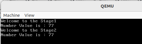
mov ax, 77
Call PrintWordNumber
call PrintNewline ; \n
;;;;;;;;;;;;;;;;;;;;;;;;;;;;;;;;;;;;;;;;;;;;;;;;;;;
; jump to the stage 2 land
jmp STAGE_2_LOAD_ADDRESS ; 0x0500
; Infinite loop
jmp $
; **************************
; Variables
; **************************
bPhysicalDriveNum db 0 ; Define variable to store disk number
WelcomeToStage1 db 'Welcome to the Stage1', 0 ; Define welcome message
; Fill out bootloader
times 510-($-$$) db 0 ; Fill up the remaining space with zeroes
; Boot Signature
db 0x55, 0xAA ; Boot signature indicating valid bootloader- Here we stored the value 77 in
axregister, printed it and immediately jump to the stage 2 loaded memory. Now we need to receive it and display on the screen in stage 2.
stage2.asm:
BITS 16

%include "boot/common/defines.inc" ; contains defintion for STAGE_2_LOAD_ADDRESS

ORG STAGE_2_LOAD_ADDRESS	; 0x0500

; Memory Map:
; 0x00000000 - 0x000004FF		Reserved
; 0x00000500 - 0x00007AFF		Second Stage Bootloader (~29 Kb)
; 0x00007B00 - 0x00007BFF		Stack Space (256 Bytes)
; 0x00007C00 - 0x00007DFF		Bootloader (512 Bytes)
; 0x00007E00 - 0x00008FFF		Used by subsystems in this bootloader
; 0x00009000 - 0x00009FFF		Memory Map
; 0x0000A000 - 0x0000AFFF		Vesa Mode Map / Controller Information
; 0x0000B000 - 0x0007FFFF		File Loading Bay

jmp stage2_entry

; Includes
%include "boot/common/print16.inc"

stage2_entry:
	mov si, WelcomeToStage2		; Print Stage 2 Welcome message
	call PrintString16BIOS
	call PrintNewline		; \n


	;;;;;;;;;;;;;;;;;;;;;;;;;;;;;;;;;;;;;;;;;;;;;;;;;;;
	;; Receive Register Passed Value from Stage 1
	;; Stage 1 Passed the value in AX
	call PrintWordNumber		; Print the Received AX value
	call PrintNewline		; \n
	;;;;;;;;;;;;;;;;;;;;;;;;;;;;;;;;;;;;;;;;;;;;;;;;;;;

jmp $

; **********
; Variables
; **********

WelcomeToStage2 db 'Welcome to the Stage2', 0
times STAGE_2_SIZE - ($-$$) db 0 ; Fill up the remaining space with zeroes- In this code, we have immediately after the entry point displayed the message which doesn't modify the value in
AXpassed by the stage 1 as these function first pushes all the register value onto the stack on starting of execution and pops the original value of all of the register before existing from the function. - Next we printed the received value in
AXfrom stage 1. - Here is the complete source code: https://github.com/The-Jat/TheTaaJ/commit/fdb58ac1dcd15b1606cd4cca3ee0d1a1b9ed6fef
Pros
- Very fast access.
- No memory management needed.
Cons
- Limited to the number of available registers.
- Data lost if registers are overwritten or if an interrupt occurs.
3️⃣ Using the Stack
Since both stages share the same stack (unless reinitialized).
Data is pushed onto the stack in stage 1 and popped off the stack in stage 2. This method is useful for passing small data without using fixed memory locations.
Steps:
- Step 1:
In stage 1, push the data onto the stack.
BITS 16
org 0x7C00

start:
    ; Set up the stack
    xor ax, ax
    mov ss, ax
    mov sp, 0x7C00

    ; Push data onto the stack
    push 77

    ; Load stage 2 bootloader (assuming it's loaded at 0x7E00)
    jmp 0x0000:0x7E00

times 510-($-$$) db 0
dw 0xAA55
- Step 2:
In stage 2, pop the data from the stack.
BITS 16
org 0x7E00

start:
    ; Pop the value from the stack
    pop ax

    ; Print the value in AX
    call PrintWordNumber
    call PrintNewline

    ; Halt the CPU
    hlt

times 512-($-$$) db 0
Complete Example:
stage1.asm:
; 16 Bit Code, Origin at 0x0
BITS 16
ORG 0x7C00
jmp main
; Includes
%include "boot/common/defines.inc" ; For constants and common variables
%include "boot/common/print16.inc" ; For printing functions
%include "boot/common/disk.inc" ; For disk read function
main:
; Disable Interrupts, unsafe passage
cli
; Far jump to fix segment registers
jmp 0x0:FixCS
FixCS:
; Fix segment registers to 0
xor ax, ax
mov ds, ax
mov es, ax
; Set stack
; The sp register is used to point to the top of the stack. By setting sp to 0x7C00, the bootloader ensures that the stack starts at the top of the memory allocated for the bootloader. This is important because the stack grows downward in memory, so it's set up before any other code runs.
mov ss, ax
mov ax, 0x7C00 ; It ensure that there's space for the stack to grow downward without overlapping with other code or any other data in memory.
mov sp, ax
; set interrupts
sti
; Save the DL register value, which contains the disk number
mov byte [bPhysicalDriveNum], dl
call ClearScreenAndResetCursor ; Clear the screen and reset the cursor
;;;;;;;;;;;;;;;;;;;;;;;;;;;;;;;;;;;;;;;;;;;;;
;; Debuggin Purpose
;;;;;;;;;;;;;;;;;;;;;;;;;;;;;;;;;;;;;;;;;;;;;
;; Print the Register value in hex and decimal
; mov ax, 1234
; mov dx, ax
; call PrintWordHex ; Print dx value in hex
; call PrintNewline ; \n
; call PrintWordNumber ; Print ax value in number
; call PrintNewline ; \n
;Print Welcome to the Screen
mov si, WelcomeToStage1 ; Load the address of the string into si register
call PrintString16BIOS ; String printing function.
call PrintNewline ; \n
; Load stage from the disk
mov dl, [bPhysicalDriveNum] ; Drive number
mov ch, 0 ; Cylinder number
mov dh, 0 ; Head number
mov cl, 2 ; Sector starting (Indexed 1, as first sector is at index 1)
mov ax, 0x0000
mov es, ax
mov bx, STAGE_2_LOAD_ADDRESS ; Memory address (0x500)
mov al, STAGE_2_SECTORS_COUNT ; 58 Number of sectors to read
call ReadFromDisk ; Call the routine to read from disk
;;;;;;;;;;;;;;;;;;;;;;;;;;;;;;;;;;;;;;;;;;;;;;;;;;;
;; Pass Data from stage 1 to stage 2,
;; through register
; mov ax, 77
; Call PrintWordNumber
; call PrintNewline ; \n
;;;;;;;;;;;;;;;;;;;;;;;;;;;;;;;;;;;;;;;;;;;;;;;;;;;
;;;;;;;;;;;;;;;;;;;;;;;;;;;;;;;;;;;;;;;;;;;;;;;;;;;
;; Pass Data from stage 1 to stage 2,
;; through known fixed memory location
;; For our example, we will pass the data by storing
;; at memory "0x7E00" which is just after the bootcode.
; mov ax, 1628
; mov word [0x7E00], ax ; Store the passing value at the location,
; by specifying size explicitly.
;; OR
;; mov [0x7E00], ax ; Store the passing value at the location
; Without specifying size explicitly, the assembler
; interprets it as to store the data of size of AX
; which is word size.
;; These both methods works, as AX is of word size,
;; so assembler only stores word size data at the location.
; Call PrintWordNumber ; Print the Passing data
; Call PrintNewline ; \n
;;;;;;;;;;;;;;;;;;;;;;;;;;;;;;;;;;;;;;;;;;;;;;;;;;;
;;;;;;;;;;;;;;;;;;;;;;;;;;;;;;;;;;;;;;;;;;;;;;;;;;;
;; Pass Data from stage 1 to stage 2 Using Stack
;; We will push the data in our stage 1
;; and pop the data from in our stage 2
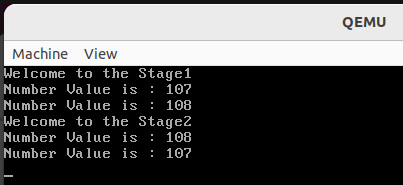
mov ax, 107 ; Set AX to the value want to pass by pushing
call PrintWordNumber ; Print the passing value
call PrintNewline ; \n
push ax ; Push AX, which is 107 on the stack
mov ax, 108 ; Change AX to 108
call PrintWordNumber ; Print Changed value
Call PrintNewline ; \n
push ax ; Push AX, which is 108 on the stack
;; Here we have passed the value 107 and 108 in the stack,
;; such that stack is:
;; | | Top (Low Memory Area)
;; | 108 |
;; |-------|
;; | 107 | Bottom (High Memory Area)
;; ---------
;; At receiving end they will be received in reverse order.
;;;;;;;;;;;;;;;;;;;;;;;;;;;;;;;;;;;;;;;;;;;;;;;;;;;
; jump to the stage 2 land
jmp STAGE_2_LOAD_ADDRESS ; 0x0500
; Infinite loop
jmp $
; **************************
; Variables
; **************************
bPhysicalDriveNum db 0 ; Define variable to store disk number
WelcomeToStage1 db 'Welcome to the Stage1', 0 ; Define welcome message
; Fill out bootloader
times 510-($-$$) db 0 ; Fill up the remaining space with zeroes
; Boot Signature
db 0x55, 0xAA ; Boot signature indicating valid bootloader- Here, we have pushed the value 107 and 108 into the stack to be passed to stage 2.
- Now top of stack is having the value 108
- Since we know that the stack is LIFO (Last-In-First-Out) meaning that the last pushed value will be popped first. Such that the data will be received in reverse order to stage 2.
- Lastly pushed data will be popped first which is 108 and so on.
stage2.asm:
BITS 16

%include "boot/common/defines.inc" ; contains defintion for STAGE_2_LOAD_ADDRESS

ORG STAGE_2_LOAD_ADDRESS	; 0x0500

; Memory Map:
; 0x00000000 - 0x000004FF		Reserved
; 0x00000500 - 0x00007AFF		Second Stage Bootloader (~29 Kb)
; 0x00007B00 - 0x00007BFF		Stack Space (256 Bytes)
; 0x00007C00 - 0x00007DFF		Bootloader (512 Bytes)
; 0x00007E00 - 0x00008FFF		Used by subsystems in this bootloader
; 0x00009000 - 0x00009FFF		Memory Map
; 0x0000A000 - 0x0000AFFF		Vesa Mode Map / Controller Information
; 0x0000B000 - 0x0007FFFF		File Loading Bay

jmp stage2_entry

; Includes
%include "boot/common/print16.inc"

stage2_entry:
	mov si, WelcomeToStage2		; Print Stage 2 Welcome message
	call PrintString16BIOS
	call PrintNewline		; \n

	;;;;;;;;;;;;;;;;;;;;;;;;;;;;;;;;;;;;;;;;;;;;;;;;;;;
	;; Receive Register Passed Value from Stage 1
	;; Stage 1 Passed the value in AX
	; call PrintWordNumber		; Print the Received AX value
	; call PrintNewline		; \n
	;;;;;;;;;;;;;;;;;;;;;;;;;;;;;;;;;;;;;;;;;;;;;;;;;;;


	;;;;;;;;;;;;;;;;;;;;;;;;;;;;;;;;;;;;;;;;;;;;;;;;;;;
	;; Receive the Fixed Known Memory Location Passed value from Stage 1
	;; In our case the known memory location is "0x7E00"
	;; and passed data is of 16 bit.
	; mov ax, [0x7E00]		; Read word size data from the location, without
					; specifying size explicitly, assembler treats it as
					; to read data of size of AX from the location which
					; is of word size.
	;; OR,
	;; mov word ax, [0x7E00]		; Read word size data from the location by,
					; specifying size explicitly.

	; call PrintWordNumber		; Print the received data
	; call PrintNewline		; \n
	;;;;;;;;;;;;;;;;;;;;;;;;;;;;;;;;;;;;;;;;;;;;;;;;;;;


	;;;;;;;;;;;;;;;;;;;;;;;;;;;;;;;;;;;;;;;;;;;;;;;;;;;
	;; Received the Stack passed value.
	;; The value will be received in reverse order,
	;; such that the value pushed lastly in stage 1 will be the one
	;; which will be popped first from the stack
	;;	|		| Top (Low Memory Area)
	;;	|  108	|
	;;	|-------|
	;;	|  107	| Bottom (High Memory Area)
	;;	---------
	pop ax		; pop the lastly passed data, which is 108
	call PrintWordNumber	; Print the received value from AX
	call PrintNewline	; \n

	pop ax		; pop the first passed data, which is 107
	call PrintWordNumber	; Print the received data from AX
	call PrintNewline	; \n
	;;;;;;;;;;;;;;;;;;;;;;;;;;;;;;;;;;;;;;;;;;;;;;;;;;;

jmp $

; **********
; Variables
; **********

WelcomeToStage2 db 'Welcome to the Stage2', 0
times STAGE_2_SIZE - ($-$$) db 0 ; Fill up the remaining space with zeroes- Here we are popping the received data through stack into ax and printing them one by one.
- They will be received in the reverse order from the order the pushed into the stack.
- You can checkout the complete source code here: https://github.com/The-Jat/TheTaaJ/tree/f146add0155044c24bf0047a8f01df920b366adf
Pros
- No fixed memory locations required.
- Flexible and easily managed.
Cons
- Stack space is limited.
- Care must be taken not to overwrite the stack.
4️⃣ Using BIOS Data Area
The BIOS Data Area (BDA) is a reserved memory region used by BIOS and the operating system. Specific addresses in the BDA can be used to store data temporarily.
The BIOS Data Area (BDA) is a reserved region of memory in IBM PC-compatible computers, typically located in the first 1 KB of conventional memory, starting at physical address 0x400. This area is used by the BIOS (Basic Input / Output System) to store various system parameters and configuration data that are crucial for hardware and system functionality. The BDA is established during the system's power-on self-test (POST) and is used by both the BIOS and the operating system to access hardware information.
Key Uses of the BIOS Data Area
- Storing Hardware Configuration: Information about the system's hardware configuration, such as the number of disk drives, keyboard status, and display configuration, is stored in the BDA.
- System Timing: Timer and clock-related data are maintained in this area to manage system time and delays.
- Communication Ports: Addresses and statuses of communication ports (serial and parallel ports) are kept here.
- Memory Size: The amount of conventional memory and extended memory is recorded in the BDA.
5️⃣ Using Disk Storage (Persistent & Large Data)
Data is written to a predefined location on disk in stage 1 and read back in stage 2. This method is useful for large amounts of data or when persistence between reboots is required.
Pros
- Can handle large amounts of data.
- Persistence between reboots.
Cons
- Slower due to disk I/O operations.
- More complex implementation.
6️⃣ Using a Data Structure in Memory
For more complex data, a structured approach can be used. Stage 1 writes a data structure to a known memory location, and Stage 2 reads from it.
; Stage 1: Store data structure in memory
org 0x7C00

section .data
data_struct:
    db 0x80   ; Example disk number
    dw 0x1234 ; Example additional data

section .text
start:
    ; Copy data structure to a known location (e.g., 0x9000:0x0000)
    mov si, data_struct
    mov di, 0x0000
    mov es, 0x9000
    mov cx, 3     ; Number of bytes to copy
    rep movsb

    ; Load Stage 2 bootloader
    ; (Assume stage2.bin starts at 0x7E00)
    mov ax, 0x07E0
    mov es, ax
    mov bx, 0x0000
    ; Load 512 bytes from disk (code to load sector omitted for brevity)
    ; ...

    ; Jump to Stage 2
    jmp 0x07E0:0000

times 510-($-$$) db 0
dw 0xAA55
; Stage 2: Read data structure from memory
org 0x7E00

section .text
start:
    ; Copy data structure from known location (e.g., 0x9000:0x0000)
    mov si, 0x0000
    mov ds, 0x9000
    mov di, data_struct
    mov cx, 3     ; Number of bytes to copy
    rep movsb

    ; Use the data as needed
    mov al, [data_struct]    ; Disk number
    mov bx, [data_struct+1]  ; Additional data

    ; Now AL and BX contain the data passed by Stage 1
    ; ...

    ; Halt the CPU
    hlt

section .data
data_struct:
    db 0x00   ; Disk number placeholder
    dw 0x0000 ; Additional data placeholder

times 512-($-$$) db 0

Leave a comment
Your email address will not be published. Required fields are marked *