In this chapter we will load the kernel of size 1 KB from the stage 2 using Extended BIOS Disk read function, which is INT 0x13 and AH = 0x42.
- Our kernel will be in real mode only.
- It will print welcome string.
You can learn more about this function at: https://thejat.in/learn/real-mode-disk-operations, Here, I have explained it in depth.
1️⃣ A Little Flash Back
There are two ways of addressing the disk. One is CHS (Cylinder, Head, Sector) while the other is LBA (Logical Block Address).
1.1 CHS (Cylinder-Head-Sector)
CHS (Cylinder-Head-Sector) is an older method for addressing data on a hard drive. It divides the hard drive into a three-dimensional space, much like a grid, allowing data to be accessed by specifying three coordinates: the cylinder number, the head number, and the sector number.
INT 0x13, AH = 0x02is the BIOS interrupt call used to read sectors from a disk using CHS addressing.
Components of CHS
- Cylinder: Represents a track through all the platters. Each platter has several tracks, and a stack of tracks across platters forms a cylinder.
- Head: Refers to the read/write head of the disk. Each platter has two surfaces, each with a read/write head. The head number specifies which surface to use.
- Sector: A subdivision of a track. Each track is divided into several sectors, usually 512 bytes each. The sector number is 1-based.
Limitations of CHS
- Limited Address Space: CHS addressing is limited by the maximum values for cylinders, heads, and sectors. Traditional CHS limits were 1024 cylinders, 256 heads, and 63 sectors per track, leading to a maximum addressable space of about 7.84 GB (1024*256*63*512 = 8,455,716,864 bytes).
- Complexity: Managing CHS addressing is more complex compared to linear addressing, especially with modern drives that have variable sector sizes and more intricate geometries.
1.2 LBA (Logical Block Addressing)
LBA (Logical Block Addressing) is a more modern and straightforward method of addressing data on a hard drive. It treats the disk as a continuous array of blocks, each with a unique address, starting from 0 up to the total number of sectors minus one.
INT 0x13, AH = 0x42is used for reading disks using LBA addressing.- It uses DAP (Disk Address Packet), which specifies
- Number of blocks (sectors) to read.
- Location where to store the read data.
- Starting Logical Block (Sector) address.
- It uses DAP (Disk Address Packet), which specifies
Advantages of LBA
- Simplicity: LBA abstracts the physical details of the disk, making it easier to manage and use.
- Greater Capacity: LBA supports larger disks by using a 48-bit or 64-bit addressing scheme, significantly increasing the addressable space.
- Compatibility: Modern operating systems and BIOS implementations prefer LBA due to its simplicity and scalability.
How LBA Works
Each block (usually 512 bytes) on the disk is assigned a unique number, starting from 0. To read or write data, you specify the LBA of the block. For example, the first block is LBA 0, the second block is LBA 1, and so on.
2️⃣ Load Kernel of Size 1 KB at Location 0x0B00
We will be loading the kernel written in assembly at a location 0x0b00. Initially the kernel would be of size 1 KB. It is just for demo purpose. Will later see, how to load the kernel of size more than 1MB using unreal mode.
Below is our code:
Kernel.asm:
org 0xB000               ; Set the origin address for the code. This tells the assembler
                         ; that the code should be loaded at memory address 0xB000.

BITS 16                  ; Specify that the code is 16-bit.

kernel_entry:            ; Label for the kernel entry point.

mov si, sKernelWelcomeStatement
                         ; Load the address of the welcome message string into SI register.

printString:
lodsb                    ; Load the byte at [SI] into AL and increment SI.
test al, al              ; Test if AL is zero.
je .printDone            ; If AL is zero, jump to .printDone label (end of string).
mov ah, 0x0e             ; Set AH to 0x0E, the BIOS teletype function for displaying characters.
int 0x10                 ; Call BIOS interrupt 0x10 to display the character in AL.
jmp printString          ; Repeat the loop to print the next character.

.printDone:
jmp $                    ; Infinite loop to halt execution after printing the message.

sKernelWelcomeStatement: db 'Welcome to Flat Binary Kernel Land', 0
                         ; Define the welcome message string, terminated by a null byte (0).

times 1024 - ($ - $$) db 0
                         ; Fill the rest of the 1 KB (1024 bytes) space with zeros.
-: Detailed Explanation :-
org 0xB000:
- Sets the origin of the code to 0xB000.
- This tells the assembler that the code will be loaded starting at address 0xB000 in memory.
- Important for ensuring that all memory addresses and jumps are calculated correctly based on this starting address.
BITS 16:
- Specifies that the code is written for a 16-bit processor mode.
- Necessary for compatibility with BIOS interrupts and the 16-bit real mode of x86 processors.
kernel_entry::
- Defines the entry point of the kernel code.
- This is where execution starts when the kernel is loaded.
mov si, sKernelWelcomeStatement:
- Loads the address of the string
sKernelWelcomeStatementinto the SI register. SIwill be used to access each character of the string sequentially.
lodsb:
- Loads the byte at the address pointed to by
SIinto the AL register. - Increments
SIto point to the next byte.
test al, al:
- Tests the AL register by performing a bitwise AND with itself.
- Sets the zero flag if AL is zero.
je .printDone:
- Jumps to the
.printDonelabel if the zero flag is set (indicating the end of the string).
mov ah, 0x0e:
- Sets AH to 0x0E, which is the BIOS teletype function for printing characters.
int 0x10:
- Calls BIOS interrupt 0x10 to display the character in the AL register.
jmp printString:
- Jumps back to the
printStringlabel to print the next character in the string.
.printDone::
- Label for the end of the string printing loop.
jmp $:
- An infinite loop to halt execution after printing the welcome message.
jmp $means jump to the current address, effectively creating an infinite loop.
sKernelWelcomeStatement: db 'Welcome to Flat Binary Kernel Land', 0:
- Defines a string terminated by a null byte (0).
- This string will be printed by the kernel.
times 1024 - ($ - $$) db 0:
- Fills the remaining space up to 1 KB (1024 bytes) with zeros.
- Ensures the binary is exactly 1 KB in size.
-: Importance of the org Directive :-
Not specifying the org directive in your assembly code can lead to incorrect addressing and jumps, as the assembler will assume a default origin (often 0x0000) which may not match the actual load address of the code in memory. This discrepancy can cause jump instructions and memory references to point to incorrect locations, leading to unexpected behavior or crashes.
- Address Calculation: The
orgdirective informs the assembler of the starting address for the code. This ensures that all labels, jumps, and memory references are calculated correctly relative to this starting address. - Memory Layout: Without specifying the correct origin, the assembler defaults to a starting address (often 0x0000), which might not match the actual load address in the system memory.
- Correct Functionality: When the code is loaded at a different address than what the assembler assumed, the jump instructions and memory accesses will not function correctly.
-: Issues Without org :-
- Incorrect Addresses: The assembler will assume the code starts at address 0x0000. If the code is actually loaded at 0xB000, all addresses will be off by 0xB000.
- Incorrect Jumps: The jump instructions will not point to the correct addresses if the code is loaded at a different address than assumed.
- Data Access: Access to data (like strings) will also be incorrect because the addresses will be calculated based on the wrong starting point.
-: Example Impact on Jumps :-
If you load the code at 0xB000 but the assembler assumed it starts at 0x0000, a jump to printString (which the assembler thinks is at, say, 0x0004) will actually jump to 0x0004 instead of the correct address 0xB004.
disk.inc:
This file will consist the code to load the kernel using extended bios function. As we know that our:
- Stage1 is of 512 Byte, so it will sit on first sector of the disk.
- Stage2 will be of 29 KB (which means 58 sector) starting from second sector and ends at sector 59.
- Kernel will be of 1 KB means 2 sectors, starting at sector 60 and ending at sector 61.
; **************************
; BIOS ReadSectorUsingExtendedBIOSFunction
; IN:
; 	- ES:BX: Buffer address
;	- EAX: Sector start (low-dword)
;	- ESI: Sector start (high-dword)
; 	- ECX: Sector count
; 	- EDX: Sector size in bytes
;
; Registers:
; 	- Conserves all but ES:BX
; **************************
ReadSectorUsingExtendedBIOSFunction:
	pushad                          ; Save all general-purpose registers on the stack

	; Set initial buffer address in DiskPackage
	mov 	word [DiskPackage.Segment], es
	mov 	word [DiskPackage.Offset], bx
	; Set initial sector start address in DiskPackage
	mov 	dword [DiskPackage.Sector], eax
	mov 	dword [DiskPackage.Sector + 4], esi

	.sLoop:
		; Setup Disk Address Packet (DAP) to read 1 sector
		mov 	word [DiskPackage.SectorsToRead], 1

		; Setup INT 0x13 Extended Read parameters
		push 	edx                  ; Save EDX (sector size in bytes)
		mov 	al, 0                ; Clear AL (used by some BIOSes)
		mov 	ah, 0x42             ; Set AH to 0x42 (Extended Read)
		mov 	dl, byte [bDriveNumber] ; Set DL to the drive number
										; bDriveNumber should have the drive number, and it is declared in stage2.asm where drive number has been stored in it.
		mov 	si, DiskPackage      ; Load DS:SI with address of DiskPackage
		int 	0x13                 ; BIOS interrupt to read sector

		; Check for buffer offset overflow
		pop 	edx                  ; Restore EDX (sector size in bytes)
		mov 	ax, word [DiskPackage.Offset]
		add 	ax, dx               ; Add sector size to offset
		mov 	word [DiskPackage.Offset], ax
		test 	ax, ax               ; Test if offset has overflowed
		jne 	.NoOverflow          ; Jump if no overflow

	.Overflow:
		; Handle buffer offset overflow by adjusting segment
		add 	word [DiskPackage.Segment], 0x1000 ; Increment segment by 0x1000
		mov 	word [DiskPackage.Offset], 0x0000  ; Reset offset to 0

	.NoOverflow:
		; Loop to read the next sector
		inc 	dword [DiskPackage.Sector] ; Increment sector number
		loop 	.sLoop                 ; Decrement ECX and loop if not zero

	.End:
	; Restore registers
	popad                           ; Restore all general-purpose registers

	; Save position in ES:BX
	push 	eax                    ; Save EAX
	xor 	eax, eax               ; Clear EAX
	mov 	ax, word [DiskPackage.Segment]
	mov 	es, ax                 ; Load ES with segment address
	mov 	bx, word [DiskPackage.Offset]
	pop 	eax                    ; Restore EAX
ret                            ; Return from the procedure

; This is used for the extended read function (int 0x13)
DiskPackage:				db 0x10
							db 0
	.SectorsToRead			dw 0
	.Offset					dw 0
	.Segment 				dw 0
	.Sector 				dq 0
Detailed Breakdown
1 Push General-Purpose Registers:
pushad: Saves all general-purpose registers to the stack. This ensures that the function does not alter the caller's register values.
2 Set Initial Buffer Address:
mov word [DiskPackage.Segment], es: Stores the segment part of the buffer address in theDiskPackagestructure.mov word [DiskPackage.Offset], bx: Stores the offset part of the buffer address in theDiskPackagestructure.
3 Set Initial Sector Start Address:
mov dword [DiskPackage.Sector], eax: Stores the low-dword of the starting LBA in theDiskPackagestructure.mov dword [DiskPackage.Sector + 4], esi: Stores the high-dword of the starting LBA in theDiskPackagestructure.
4 Loop to Read Sectors:
.sLoop:: Label marking the start of the loop for reading sectors.mov word [DiskPackage.SectorsToRead], 1: Sets theSectorsToReadfield in theDiskPackageto 1, indicating one sector to read per iteration.
5 Setup BIOS Interrupt for Extended Read:
push edx: SavesEDX(sector size in bytes).mov al, 0: ClearsAL.mov ah, 0x42: SetsAHto 0x42 for the Extended Read function.mov dl, byte [bDriveNumber]: Loads the drive number intoDL.mov si, DiskPackage: Loads the address of theDiskPackagestructure intoSI.int 0x13: Calls the BIOS interrupt to read a sector.
6 Check for Buffer Offset Overflow:
pop edx: RestoresEDX.mov ax, word [DiskPackage.Offset]: Loads the current buffer offset.add ax, dx: Adds the sector size to the offset.mov word [DiskPackage.Offset], ax: Stores the new offset.test ax, ax: Tests if the offset has overflowed (i.e., wrapped around to zero).jne .NoOverflow: Jumps to.NoOverflowif there was no overflow.
7 Handle Buffer Offset Overflow:
.Overflow:: Label for handling overflow.add word [DiskPackage.Segment], 0x1000: Increments the buffer segment by 0x1000.mov word [DiskPackage.Offset], 0x0000: Resets the buffer offset to zero.
8 Increment Sector Number and Loop:
.NoOverflow:: Label for continuing after handling potential overflow.inc dword [DiskPackage.Sector]: Increments the starting LBA for the next sector.loop .sLoop: DecrementsECX(sector count) and loops if it is not zero.
9 Restore Registers and Save Position:
.End:: Label marking the end of the loop.popad: Restores all general-purpose registers from the stack.push eax: SavesEAX.xor eax, eax: ClearsEAX.mov ax, word [DiskPackage.Segment]: Loads the final buffer segment.mov es, ax: Stores it inES.mov bx, word [DiskPackage.Offset]: Loads the final buffer offset.pop eax: RestoresEAX.ret: Returns from the function.
DiskPackage Structure
This structure is used to pass parameters to the BIOS interrupt for the extended read operation. It contains fields for the buffer segment and offset, the number of sectors to read, and the starting LBA.
It contains the four information:
- Buffer segment,
- Buffer offset
- Number of sectors to read
- Reading Starting Sector (LBA, 0-indexed)
stage2.asm:
This is our stage 2 main code. Inside of it we will call the reading function which reads from the disk using the extended read function.
We will load the kernel at memory location 0xB000. We will read a total of 2 block (sectors). For the time being our kernel is just born. It is tiny.
xor eax, eax		; clear out the eax
mov es, ax			; set extra segment to 0x0000
mov bx, 0xb000		; set offset to 0xb000
mov eax, 59			; starting sector low 32 bit
					; LBA (starting from the 0
					;	for the first sector.)
mov esi, 0			; starting sector high 32 bit
mov cx, 2			; sector count
mov edx, 512		; sector size in bytes
call ReadSectorUsingExtendedBIOSFunctionMakefile:
We need to modify the makefile as well. Because we need to write the every binary file to the particular position in the disk image using dd command.
# $@ = target file
# $< = first dependency
# $^ = all dependencies

BOOT_STAGE_INCLUDE = boot/common
BOOT_STAGE2_INCLUDE = boot/stage2/includes

all: build_dir boot disk.img run
#boot run

build_dir:
	mkdir -p build

stage1.bin: boot/stage1/stage1.asm
	nasm -f bin -I $(BOOT_STAGE_INCLUDE) -o build/$@ $<

stage2.bin: boot/stage2/stage2.asm
	nasm -f bin -I $(BOOT_STAGE_INCLUDE) -I $(BOOT_STAGE2_INCLUDE) -o build/$@ $<

kernel_entry.bin: kernel/kernel_entry.asm
	nasm -f bin -o build/$@ $<

# concatenate the both stages of bootloader
boot: stage1.bin stage2.bin kernel_entry.bin
	cat build/stage1.bin build/stage2.bin build/kernel_entry.bin > build/boot.bin

disk.img: stage1.bin stage2.bin kernel_entry.bin
	dd if=/dev/zero of=build/disk.img bs=512 count=2880
	dd if=build/stage1.bin of=build/disk.img bs=512 seek=0 conv=notrunc
	dd if=build/stage2.bin of=build/disk.img bs=512 seek=1 conv=notrunc
	dd if=build/kernel_entry.bin of=build/disk.img bs=512 seek=59 conv=notrunc

run:
	# qemu-system-x86_64 -drive  format=raw,file=build/boot.bin
	qemu-system-x86_64 -drive  format=raw,file=build/disk.img


# Clean up generated files
clean:
	rm -rf build
Explained:
The few changes which are here from the last makefile. In this makefile we manually write binary files to particular location in disk image.
# Create an empty disk image
dd if=/dev/zero of=build/disk.img bs=512 count=2880

# Write stage1.bin to the first sector (MBR)
dd if=build/stage1.bin of=build/disk.img bs=512 seek=0 conv=notrunc

# Write stage2.bin to the second sector
dd if=build/stage2.bin of=build/disk.img bs=512 seek=1 conv=notrunc

# Write kernel_entry.bin to sector 59
dd if=build/kernel_entry.bin of=build/disk.img bs=512 seek=59 conv=notrunc
3️⃣ Output
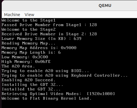
4️⃣ Source Code
You can get the complete source code at this point, Here: https://github.com/The-Jat/TheTaaJ/tree/c060a915f988a21e09f0076eab0ec4e66e3019fc

Leave a comment
Your email address will not be published. Required fields are marked *