When an x86 processor boots up, it starts in real mode, which is backward compatible to 8086.
Real mode is the simplest operating mode of x86 CPUs, where the processor operates as a simple 16-bit processor with access to 1MB of memory. In real mode, there is no memory protection or multitasking, and all memory addresses correspond directly to physical memory addresses. This mode is used during the early boot process of a computer.
In this mode we have BIOS interrupts to interact with the hardware, like printing to screen, reading key stroke input, reading data from disk, and much more. One of them is int 0x10.
Prerequisites
This complete guide is for the Linux (Ubuntu in particular).
Before we begin, we have to set the environment. We would need an assembler like NASM (Netwide Assembler) and an emulator like QEMU to test your code.
You can install NASM and QEMU on most linux distributions using package managers like apt or yum:
sudo apt-get install nasm qemu
Steps Involved:
Step 1:
- An assembly file (
stage1boot.asm) that will use interrupt function to display on screen. - It would be of size 512 bytes. As it will be placed on the boot sector of the disk which is 512 bytes long.
Step 2:
- Assemble the assembly file mentioned above using
NASMassembler to generate binary file.
Step 3:
- Emulate the generated file using
QEMU.
1 stage1boot.asm:
The main assembly file which is the entry point of the our stage 1 booting.
; stage1boot.asm
[org 0x7c00] ; Set the origin to 0x7C00, where the BIOS loads the boot sector
mov [BOOT_DISK], dl ; Save the boot disk number (passed by BIOS in DL) to BOOT_DISK
mov bx, MSG_REAL_MODE ; Load the address of the message into BX
call print_string ; Call the print_string function to print the message
jmp $ ; Infinite loop to halt execution
%include "utils16/print.asm" ; Include the print_string function from an external file
MSG_REAL_MODE:
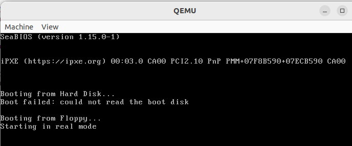
db 'Starting in real mode', 0 ; Null-terminated string
BOOT_DISK: db 0 ; Variable to store the boot disk number
times (510-($-$$)) db 0 ; Pad the rest of the boot sector with zeros
db 0x55 ; Boot sector signature (part 1)
db 0xaa ; Boot sector signature (part 2)
Step-by-Step Booting Process:
1 Power On and POST (Power-On Self-Test):
- When the computer is powered on, the CPU is initialized, and the BIOS (Basic Input/Output System) runs a POST to check the hardware components.
- If the POST completes successfully, the BIOS proceeds to locate a bootable device.
2 BIOS Loads the Bootloader:
- The BIOS searches for a bootable device by looking for a valid boot sector, which is the first 512 bytes of a storage device (e.g., hard drive, floppy disk).
- A valid boot sector ends with the signature bytes
0x55AA.
3 Execution of Boot Sector:
- Once the BIOS finds a valid boot sector, it loads these 512 bytes into memory at address
0x7C00and transfers control to this location by setting the instruction pointer (IP) to0x7C00.
4 Bootloader Initialization:
- The CPU starts executing the bootloader code at address
0x7C00. - The first instruction in your bootloader is
[org 0x7C00], which tells the assembler that this code is intended to be loaded and run from the address0x7C00.
5 Save Boot Disk Number:
- The boot disk number, which is passed by the BIOS in the
DLregister, is saved to theBOOT_DISKvariable.
6 Load Message Address:
- The address of the message string (
MSG_REAL_MODE) is loaded into theBXregister.
7 Call print_string Function:
- The
print_stringfunction is called to print the message.
8 Print String Function Execution:
- The
print_stringfunction begins execution. - All general-purpose registers are saved using
pusha. - A loop is started that reads each character of the message string from memory and prints it using BIOS interrupt
0x10. - The loop continues until it encounters the null terminator (
0). - The registers are restored with
popa, and control returns to the caller.
9 Infinite Loop:
- After returning from the
print_stringfunction, the bootloader enters an infinite loop to halt further execution.
2 utils16/print.asm:
; utils16/print.asm

[bits 16] 	; Specify 16-bit code

print_string:
    pusha                        ; Save all general-purpose registers
    mov ah, 0x0e                 ; Set AH to BIOS teletype output function
print_string_cycle:
    cmp [bx], BYTE 0             ; Compare the byte at address BX with 0 (null terminator)
    je print_string_end          ; If zero (null terminator), jump to the end
    mov al, [bx]                 ; Load the byte at address BX into AL
    int 0x10                     ; Call BIOS interrupt 0x10 to print the character in AL
    add bx, 1                    ; Increment BX to point to the next character
    jmp print_string_cycle       ; Repeat the loop
print_string_end:
    popa                         ; Restore all general-purpose registers
    ret                          ; Return from the function
Explanation:
1 Function Entry:
pusha
- Saves all general-purpose registers to ensure they are not modified during the function execution.
2 Set Up BIOS Teletype Function:
mov ah, 0x0e
- Sets
AHto0x0E, which is the BIOS teletype output function. This function prints the character inALto the screen.
3 Print Loop Start:
print_string_cycle:
cmp [bx], BYTE 0
je print_string_end
- The loop starts by comparing the byte at address
BXwith0(null terminator). - If the byte is
0, it jumps to theprint_string_endlabel to terminate the loop.
4 Load Character:
mov al, [bx]
- Loads the byte at address
BX(current character in the string) intoAL.
5 Call BIOS Interrupt:
int 0x10
- Calls BIOS interrupt
0x10, which prints the character inALusing the teletype output function.
6 Increment Pointer:
add bx, 1
- Increments
BXto point to the next character in the string.
7 Repeat Loop:
jmp print_string_cycle
- Jumps back to the start of the loop to process the next character.
8 End of String:
print_string_end:
popa
ret
- Once the null terminator is encountered, the function restores the general-purpose registers with
popaand returns to the caller withret.
3 Makefile
Now its time to assemble the assembly file and emulate it. We will use Makefile to easy our task, so that it tracks changes and generate binary file and run, all in simple make command.
# $@ = target file
# $< = first dependency
# $^ = all dependencies

# Define phony targets to avoid conflicts with files of the same name
.PHONY: all run clean

# Default target to build everything and run the OS image
all: run

# Rule to assemble the stage1boot.asm file into a binary file stage1boot.bin
stage1boot.bin: stage1boot.asm
	nasm $< -f bin -o $@

# Rule to run the OS image using QEMU
run: stage1boot.bin
	qemu-system-x86_64 -fda $<

# Clean up generated files
clean:
	rm -rf *.bin *.o
3.1 Detailed Breakdown
1 Phony Targets:
.PHONY: all run clean
- Declares
all,run, andcleanas phony targets to ensure that Make treats them as commands rather than file names.
2 Default Target:
all: run
- The default target when
makeis run without arguments. It depends on theruntarget, somake allwill execute theruntarget.
3 Assembling the Bootloader:
stage1boot.bin: stage1boot.asm
	nasm $< -f bin -o $@
- This rule tells Make how to build
stage1boot.binfromstage1boot.asm. $<is a special variable that refers to the first dependency (stage1boot.asm).$@is a special variable that refers to the target file (stage1boot.bin).- The command
nasm $< -f bin -o $@invokes NASM to assemble the assembly file into a binary format.
4 Running the OS Image:
run: stage1boot.bin
qemu-system-x86_64 -fda $<- This rule specifies how to run the OS image using QEMU.
rundepends onstage1boot.bin.$<refers to the first dependency (stage1boot.bin).- The command
qemu-system-x86_64 -fda $<runs QEMU withstage1boot.binas the floppy disk image.
3.2 Usage
1 Build and Run:
To build and run the bootloader, simply run:
make
- This will assemble
stage1boot.asmand createstage1boot.bin, and run it with QEMU.
2 Clean Up:
To clean up generated files, run:
make clean4 Output

Leave a comment
Your email address will not be published. Required fields are marked *