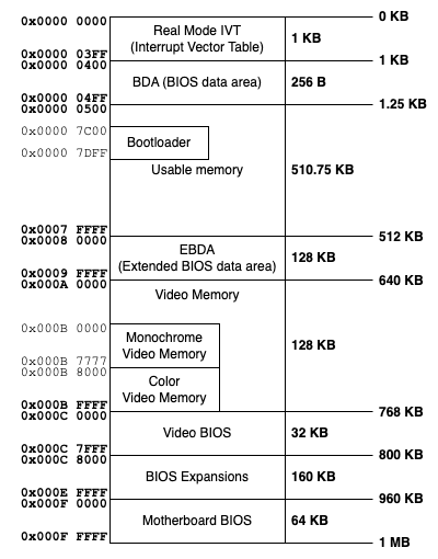
After the BIOS transfers control to boot sector, the first megabyte of memory looks like this:
| Address: Segment:Offset | Size | Name |
| 0x0000:0x0000 | 1024 bytes | Interrupt Vector Table |
| 0x0040:0x0000 | 256 bytes | BIOS Data Area |
| 0x0050:0x0000 | ? | Free memory |
| 0x07C0:0x0000 | 512 bytes | Boot sector code |
| 0x07E0:0x0000 | ? | Free memory |
| 0xA000:0x0000 | 64 Kb | Graphics Video Memory |
| 0xB000:0x0000 | 32 Kb | Monochrome Text Video Memory |
| 0xB800:0x0000 | 32 Kb | Color Text Video Memory |
| 0xC000:0x0000 | 256 Kb1 | ROM Code Memory |
| 0xFFFF:0x0000 | 16 bytes | More BIOS data |
BIOS Data Area (BDA)
The BIOS Data Area (BDA) is a reserved region of memory in IBM PC-compatible computers, typically located in the first 1 KB of conventional memory, starting at physical address 0x400. This area is used by the BIOS (Basic Input/Output System) to store various system parameters and configuration data that are crucial for hardware and system functionality. The BDA is established during the system's power-on self-test (POST) and is used by both the BIOS and the operating system to access hardware information.
- It is used to store important system information.
- The BDA provides a standardized way to store and access various hardware and configuration parameters necessary for the BIOS, operating system, and certain applications.
Why the BIOS Data Area Exists
The BDA exists to provide a reliable and consistent location for storing critical system information that needs to be accessed by both the BIOS and the operating system. This design ensures that hardware configuration and status information is available from the moment the system boots until it is powered down or reset.
Key Uses of the BIOS Data Area
- Storing Hardware Configuration: Information about the system's hardware configuration, such as the number of disk drives, keyboard status, and display configuration, is stored in the BDA.
- System Timing: Timer and clock-related data are maintained in this area to manage system time and delays.
- Communication Ports: The addresses and statuses of serial (COM) and parallel (LPT) ports are stored in the BDA.
- Memory Size: The amount of conventional memory and extended memory is recorded in the BDA.
- Boot Information: It can store boot-related information and status flags used during the boot process.
Structure of the BIOS Data Area
The BDA starts at physical address 0x400 (segment 0x40 in real mode) and occupies 256 bytes (0x400 to 0x4FF). Here is a detailed breakdown of the BDA structure with some key offsets and the data they store:
| Offset | Length (bytes) | Description |
|---|---|---|
| 0x400 | 2 | COM1 I/O port address |
| 0x402 | 2 | COM2 I/O port address |
| 0x404 | 2 | COM3 I/O port address |
| 0x406 | 2 | COM4 I/O port address |
| 0x408 | 2 | LPT1 I/O port address |
| 0x40A | 2 | LPT2 I/O port address |
| 0x40C | 2 | LPT3 I/O port address |
| 0x40E | 2 | LPT4 I/O port address |
| 0x410 | 1 | Installed equipment list flags. Provides hardware configuration flags (e.g., floppy drives, coprocessor availability). |
| 0x411 | 2 | Base memory size (in KB) |
| 0x413 | 2 | Address of keyboard buffer head |
| 0x415 | 2 | Address of keyboard buffer tail |
| 0x417 | 32 | Keyboard buffer |
| 0x441 | 1 | Current display mode |
| 0x450 | 1 | RTC status register B |
| 0x460 | 2 | Extended memory size (in KB) |
| 0x462 | 2 | CMOS reset flag |
| 0x463 | 2 | POST status (BIOS use) |
| 0x467 | 1 | Last key scan code |
| 0x47A | 2 | Status flags for the BIOS data area |
| 0x480 | 7 | Reserved for IBM use |
| 0x484 | 2 | Number of hard disks |
| 0x4F0 | 16 | Reserved for IBM use |
For more information visit here: https://github.com/oblivia-simplex/cmoskit/blob/master/Bios_Information_Leakage.txt
What the BIOS Data Area Stores
1 Communication Port Addresses:
The BDA stores the base I/O port addresses for the serial and parallel ports, allowing software to communicate with these devices:
- COM Port Addresses:
- Stores the base
I/Oaddresses for up to four serial ports. - Address:
0x400- COM1: 0x400
- COM2: 0x402
- COM3: 0x404
- COM4: 0x406
- Stores the base
- LPT Port Address:
- Stores the base
I/Oaddresses for up to three parallel ports. - Address:
0x408- LPT1: 0x408
- LPT2: 0x40A
- LPT3: 0x40C
- LPT4: 0x40E
- Stores the base
2 Installed Equipment List:
The equipment list flag at offset 0x410 provides information about the hardware installed on the system, such as the presence of disk drives, display modes, and other peripherals.
- Indicates connected hardware, such as:
- Number of installed floppy drives.
- Availability of a math coprocessor.
- Presence of a serial/parallel port.
- Address:
00410h
3 Memory Size:
Offsets 0x411 and 0x460 store the size of conventional and extended memory, respectively. This information is crucial for memory management by the operating system:
- Base memory size: 0x411 (in KB)
- Extended memory size: 0x460 (in KB)
3 Keyboard Buffer:
The BDA includes a keyboard buffer starting at offset 0x417, which stores keystrokes before they are processed by the operating system:
- Keyboard buffer head: 0x413
- Keyboard buffer tail: 0x415
- Keyboard buffer: 0x417 (32 bytes)
- Tracks the state of the keyboard, such as:
- Shift, Ctrl, and Alt key states.
- Lock key states (Caps Lock, Num Lock, Scroll Lock).
- Address:
00417h
4 Display Mode:
Offset 0x441 stores the current display mode, which is used by the BIOS and operating system to configure the video display properly.
5 RTC and Status Flags:
The Real-Time Clock (RTC) status register B at offset 0x450 and various status flags at other offsets store time-related information and system status flags that are important for system timing and control.
References

Leave a comment
Your email address will not be published. Required fields are marked *